


 142 / 218

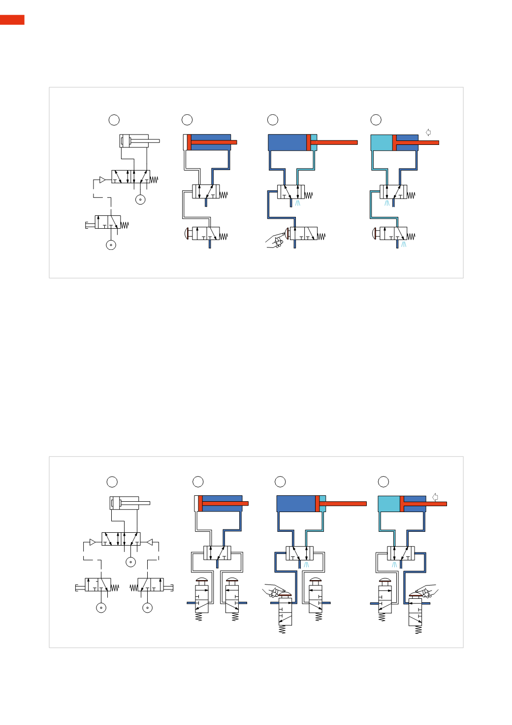
Figure 16
Pos. 4:
as the button is released, the command signal is discharged through outlet 3 of the pilot valve. The main
valve returns to rest position due to the effect of the spring, putting inlet 1 in communicationwith outlet 2. Outlet 4
is exhausted through the exhaust port 5. The piston rod/piston returns to its initial position.
1
2
3
4
1
3
5
2
4
14
12
1
2
3
12
1
2
3
12
Fig. 17
1
2
3
4
1
3
5
2
4
14
12
1
2
3
Fig. 16
Figure 17
Bistable valve, indirectly operated
Pos. 1:
with this type of main valve, two pilot signals are required; a second pilot valve is added.
Pos. 2:
the bistable 5/2-way valve does not have a definite rest position and as a consequence, either outlet 2 or 4
may be active. As none of the pilot valves are activated, in this case themain valve pressurizes the cylinder so that
the piston rod/piston is in the negative end position.
Pos. 3:
if the left push button is activated; the passage between inlet 1 and outlet 2 on the pilot valve is opened,
pressurizing the pilot port 14 of themain valve. Themain valve changes over so the outlet 2 is exhausted through
the exhaust port 3, inlet 1 is in communicationwith outlet 4, pressurizing the positive chamber of the cylinder, the
piston rod/piston reaches the positive end position. This condition is maintained even if the signal from the pilot
valve is interrupted. Upon releasing the push button, outlet 2 of the pilot valve exhausts through the exhaust port 3.
Pos. 4:
by activating the button on the right, the passage between inlet 1 and outlet 2 of the pilot valve is opened,
pressurizing the pilot port 12 of the main valve. The main valve changes over, outlet 4 exhausts through the
exhaust port 5, inlet 1 is in communication with outlet 2, pressurizing the negative chamber of the cylinder, the
piston rod/piston reaches the negative end position. This condition is maintained even if the signal from the pilot
valve is interrupted.
If the button on the rightwere to remainactivatedwhile the button on the leftwas activated, themain valvewould
receive two pilot signals but therewould be no response, as the valvewould remain in the position determined by
the first pilot signal received.
5
140
CAMOZZI
>
CIRCUIT TECHNIQUE