


 141 / 218

CIRCUIT TECHNIQUE
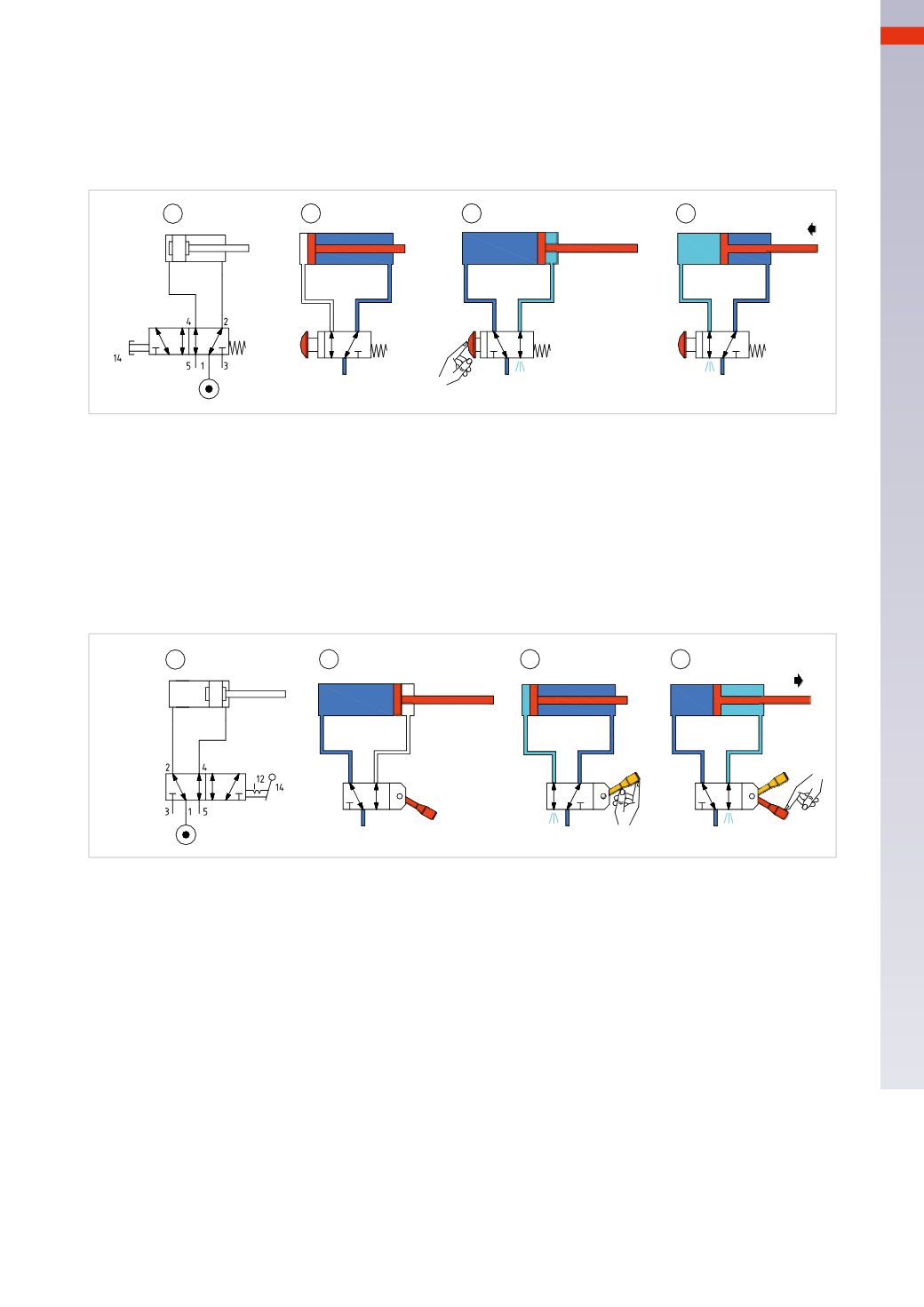
Pos. 3:
pressing and holding the push button opens the passage between inlet 1 and outlet 4, while outlet 2
connects to exhaust 3. The compressed air enables the movement of the piston rod/piston, which reaches the
positive end position.
Pos. 4:
when the push button is released, the valve returns to its rest position, resuming communication between
inlet 1 and outlet 2, while outlet 4 is in communicationwith exhaust 5. The piston rod/piston returns to the initial
position.
1
2
3
4
Fig. 14
Figure 15
Bistable valve, directly operated
Pos. 1:
the bistable 5/2-way valve does not have a definite rest position and as a consequence, either outlet 2 or
4may be active.
Pos. 2:
with the lever in this position there is passage of compressed air between inlet 1 and outlet 2. The piston
rod/piston reaches the positive end position.
Pos. 3:
by moving the lever, inlet 1 is put in communication with outlet 4 while outlet 2 is discharging through
exhaust port 3. The piston rod/pistonmoves until it reaches the negative end position.
Pos. 4:
through repositioning the lever, inlet 1 is once again in communication with outlet 2 while outlet 4 is
exhausted through the exhaust port 5. The rod/piston rod reaches the positive end position.
1
2
3
4
Fig. 15
These introductory circuit solutions are called
direct control
and represent the simplest way for controlling the
movement of a cylinder. In this circuit there is only a single valvewith a dual function: distribution and control.
It is not always convenient for the operator to directly operate a control valve, especially when located in close
proximity to the actuator. In such situations, it is possible to use a pneumatically operated valve, commanded by a
valve located in a safe ormore accessible position as an alternative. In this case, the command is no longer
direct
(as in the previous chapters), but it is now
indirect
due to the presence of the second pilot valve. The dimensions
of this valve and its connection ports can be quite small (as there is no need for a large flow rate). The actuation
forces necessary for its activation (in themanual version) can be reduced, as a high flow rate is not necessary.
Figure 16
Monostable valve, indirectly operated
Pos. 1:
the
pilot
valve is a 3/2-way monostable valve with mechanical spring return and manual operation (push
button). The
main
valve is a 5/2-waymonostable valvewithmechanical spring return and pneumatically operated.
Outlet 2 of the pilot valve is connected to the pilot port 14 of themain valve.
Pos. 2:
in the absence of a pilot signal, themain valve is at rest, the compressed air connected to inlet 1 through
outlet 2, pressurizing the negative cylinder chamber, keeping the piston rod/piston against the rear end cap.
Pos. 3:
by pressing andholding the pushbutton, the passage between inlet 1and outlet 2 is opened that commands
themainvalve. Themainvalve switches, outlet2exhausts through theexhaust port3and inlet1 is incommunication
with outlet 4. The compressed air enables themovement of the piston rod/piston, which reaches the positive end
position. This condition ismaintained as long as the operator depresses the push button on the pilot valve.
5
139
CAMOZZI
>
CIRCUIT TECHNIQUE