


 137 / 218

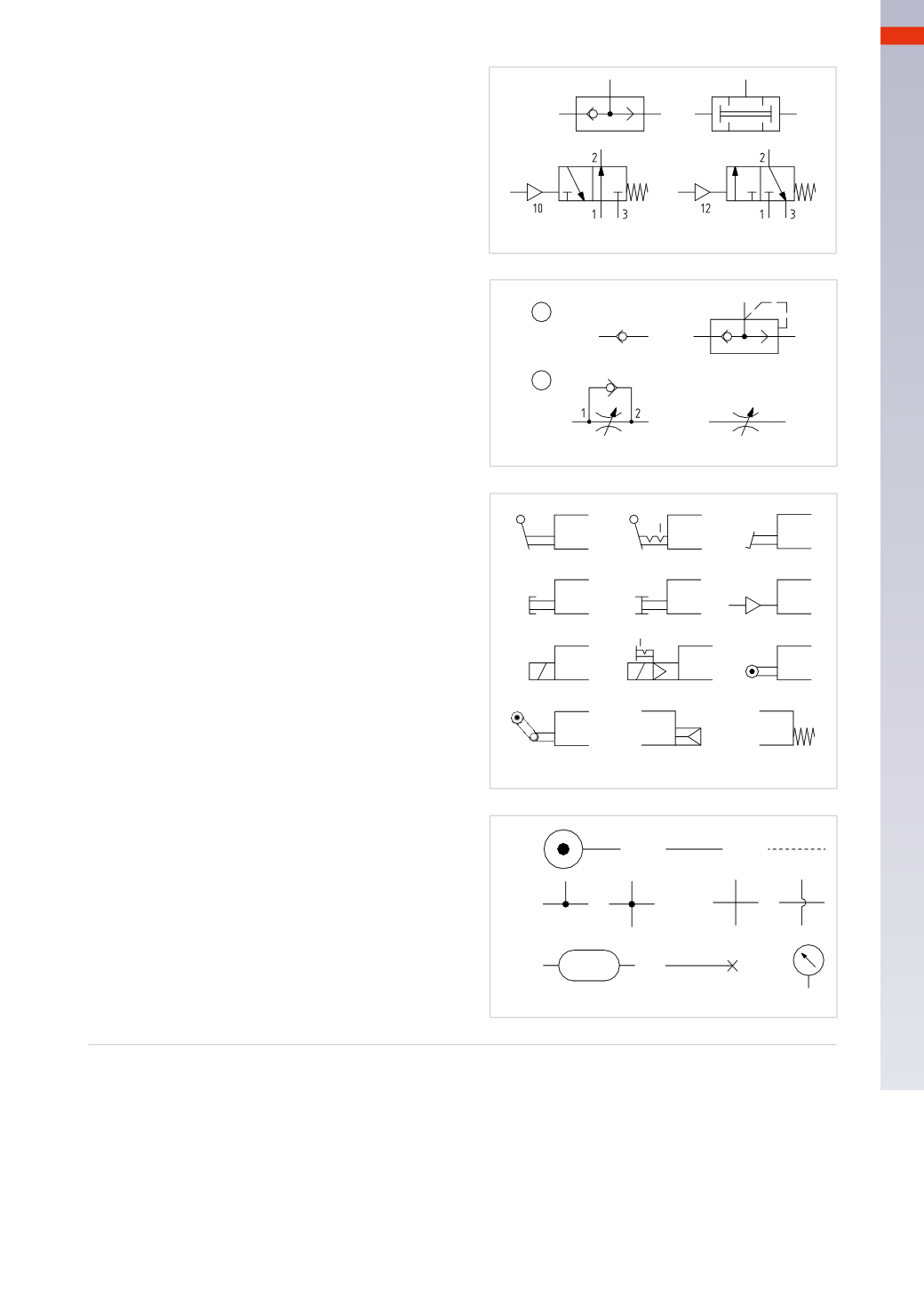
CIRCUIT TECHNIQUE
Figure 4
Logic valves
A
: function
OR
selector valve
B
: function
AND
2 input valve
C
: function
NOT
inverter valve
D
: function
YES
amplifier valve
Figure 5
Pos. 1:
Isolation interception valves
A
: non-return valve
B
: quick exhaust valve
Pos. 2:
A
: unidirectional flow regulator
B
: bidirectional flow regulator
Figure 6
Operating devices
A
: manual lever
B
: manual lever with stable position
C
: pedal
D
: manual with (mushroom) push button
E
: manual with push and pull button
F
: pneumatic pilot
G
: direct electrical - pneumatic pilot
(for solenoid valves)
H
: electro-pneumatic (solenoid pilot)
with bistablemanual override
I
: mechanical with bidirectional roller lever
M
: mechanical with unidirectional roller lever
N
: pneumatic spring return
P
: mechanical spring return
Figure 7
Additional symbols
A
: pressure source
B
: pressure line
C
: control or pilot line
D
: fixed connections
E
: passing lines
F
: capacity/reservoir
G
: closed port
H
: pressure gauge
Some symbols are to be completedwith the symbols
for the actuation and repositioning.
A
B
C
D
Fig. 4
1
2
A
B
A
B
Fig. 5
A
B
D
E
F
I
M
N
P
G
H
C
Fig. 6
A
B
C
D
E
F
G
H
Fig. 7
5
135
CAMOZZI
>
CIRCUIT TECHNIQUE