


 139 / 218

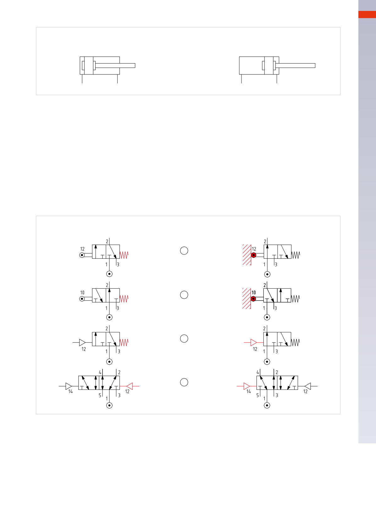
CIRCUIT TECHNIQUE
ENDSTROKENEGATIVEPOSITION
ENDSTROKEPOSITIVEPOSITION
Fig. 10
The valves are represented by two small adjacent squares, which define the positions the valve can assume.
Arrows positioned inside the squares indicate the direction of the flow of compressed air.
In the non-operated position, pneumatic connections and their relative identification numbers are illustrated in
the small square adjacent to the spring. In the operated position the external connections and the connections are
illustrated in the small square located next to the operator symbol.
Figure 11
Pos. 1:
3/2-way NC valvemechanically operatedwithmechanical spring return.
Pos. 2:
3/2-way NO valvemechanically operatedwithmechanical spring return.
Pos. 3:
3/2-wayNC valve pneumatically operatedwithmechanical spring return. The presence of the pilot signal
is not directly detectable (unlike the previous cases). The position of the external connection and valve port numbers
will indicate the presence/absence of the pilot signal.
Pos. 4:
5/2-way valve bistable pneumatically operated. The pilot ports (control signals) are positioned on the short
ends of the valve. Either outlet 2 or outlet 4 is always connected to inlet 1. The active position is indicated by the
square inwhich the external connections and port numbers are located.
NOTACTUATED
ACTUATED
1
2
3
4
Fig. 11
5
137
CAMOZZI
>
CIRCUIT TECHNIQUE