


 138 / 218

A
B
1
2
3
1
1
1
1
2
1
2
1
2
1
2 4
1
1
1
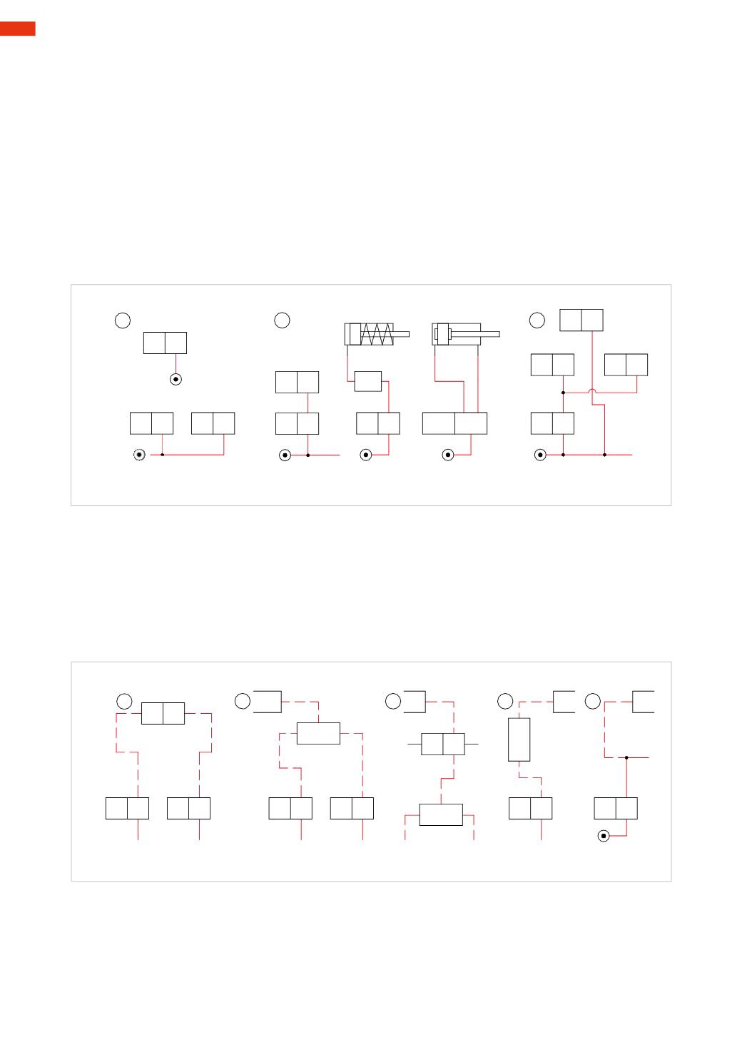
Fig. 8
Rules for designing circuits
Any circuit, regardless of whether it is electric or pneumatic, comprises a set of conventional lines and symbols
representing their respective functions, connections, and state of command at the end of cycle position. In the
previous sections we illustrated the symbols of the components. Below we demonstrate how to draw and join them
together to create a circuit.
Figure 8
Pos. 1:
A
: the pressure source is represented by a circle with a dot in the centre. It can be indicated on any component
that can receive the pressure source. The connection between the two parts is achieved via a tube.
B
: the pressure source can be illustrated as a single entity, then distributed to the various elements.
Pos. 2:
a continuous solid line is used to identify “working” or “power” tubes.
Pos. 3:
it is preferable to avoid intersecting connecting lines in the drawings wherever possible. Where it is not
possible, it is advisable to interrupt one of the two lines and form a small arc to indicate the tubes overlapping.
Connections are best highlighted with a small clearly visible dot.
With a dashed line, we represent tubes which:
Figure 9
Pos. 1:
determines the piloting of pneumatic valves
Pos. 2:
indicates whether the servo pilot of a solenoid valve is external
Pos. 3:
represents the input and output connections of the signal handling valves
Pos. 4:
indicates the inlet and outlet of the functional valves
Pos. 5:
in some cases the pipes must be represented in two ways at the outlet of a distribution valve; with a dashed
line for switching a pneumatic operated valve, and a continuous line for feeding another valve.
1
2
3
4
5
1
2
1
2
1
1
2
2
2
2
2
Fig. 9
The continuous line is generally the most represented.
The circuit drawing must represent all of the components in the position they assume when the machine/equipment
is at the end of the cycle.
Figure 10
The cylinders are represented by a rectangle, the piston rod/piston is located inside this rectangle. The position of
the piston rod indicates whether the rod is retracted or not.
5
136
CAMOZZI
>
CIRCUIT TECHNIQUE