


 161 / 218

CIRCUIT TECHNIQUE
X
K
X
K
X
K
1
2
3
X= 0
K=1
X= 1
K=0
X= 0
K=0
a
b
a
b
a
b
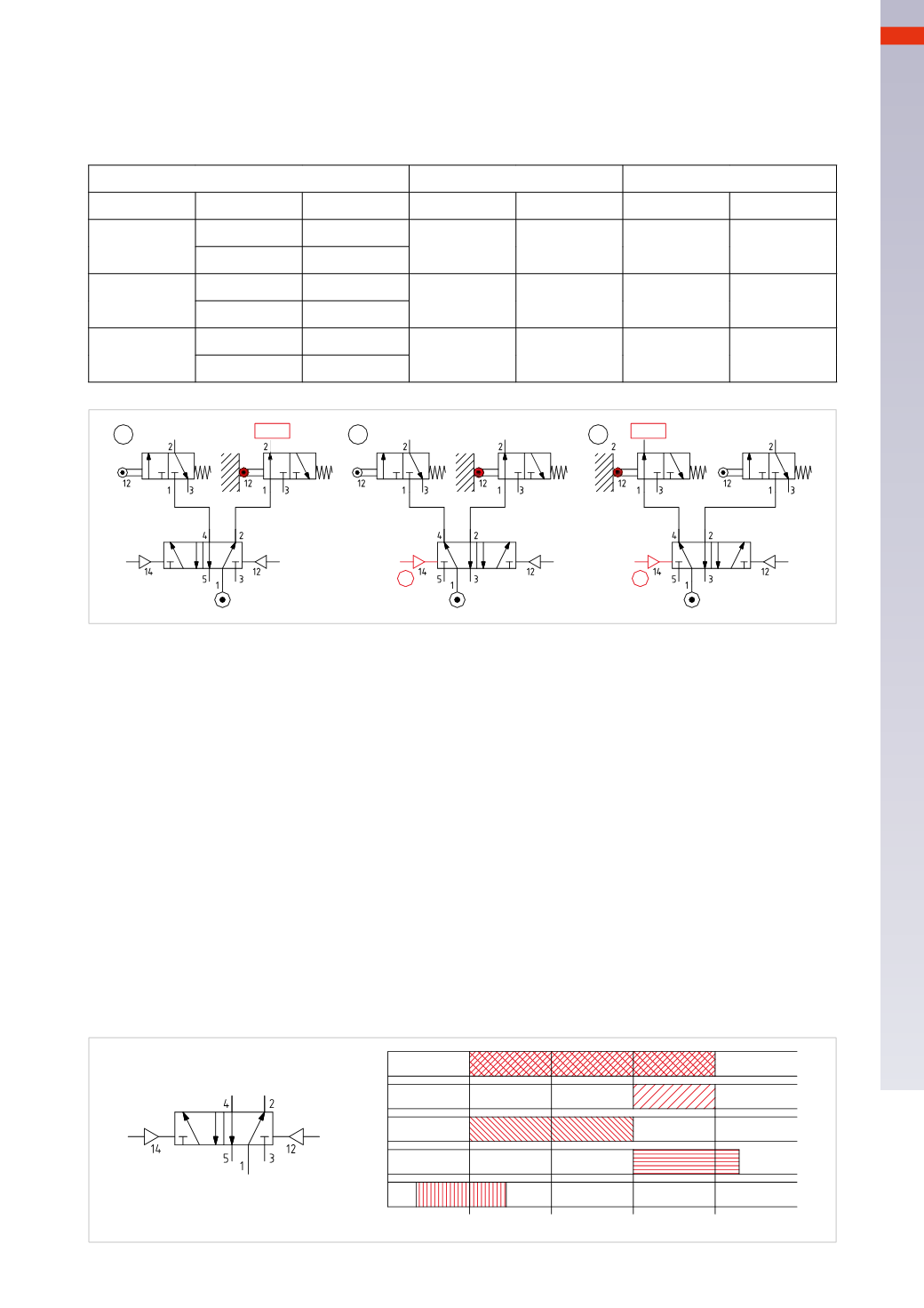
Fig. 52
Figure 52
Using thememory valve fed by the compressed air network.
Two limit switches 3/2-way NCmonostable are fed alternately by the
X
and
K
of a memory. The outputs of the
limit switches will only be present in the presence of the command on their respective actuation device.
Memory
Left limit switch
Right limit switch
Signal
Outlet
Actuation
Outlet
Actuation
Outlet
Pos. 1
a= 0
X=0
Absent
0
Present
1
b=0
K= 1
Pos. 2
a= 1
X= 1
Absent
0
Present
0
b= 0
K=0
Pos. 3
a= 0
X= 1
Present
1
Absent
0
b= 0
K= 0
Figure 53
Using thememory valve fedwith compressed air by another valve.
The outputs
X
and
K
depend on the presence of compressed air and from the signal “
a
” and “
b
”.
For ease of readability, the diagram has been divided into equal parts.
Time 0-1
: signal “
b
”, arrives; thememory is positioned in such away that in the presence of compressed air, the
outlet
K
is active.
S=0
K= 0
X= 0
Time 1-2
: signal “
b
” is interrupted, compressed air is present, thememory state does not change and the output
K
is activated.
S=
1
K=
1
X= 0
Time 2-3
: even in the absence of signal “
a
” or “
b
” thememory state does not change and remains in the position
defined by the last received signal (
b
).
Time 3-4
: signal “
a
” arrives; the memory is positioned so that the compressed air is in communication with the
outlet
X
.
S=
1
K= 0
X=
1
Time 4-5
: the compressed air is not present and there are no output signals. The presence of signal “
a
” does not
alter the situation.
S=0
K= 0
X= 0
S
S
X K
b
X
K
a
b
0
1
2
3
4
a
Fig. 53
5
159
CAMOZZI
>
CIRCUIT TECHNIQUE