


 164 / 218

_A
+
B_
+
1 2 3
1 4
I.C.
b0
a0
a1
a1
A
B
a0 a1
b1
X
a1
a0
b0 b1
b
b
a
a
b0
C.S.
C.S.
C.A.
AutomaticCycle
SingleCycle
Fig. 59
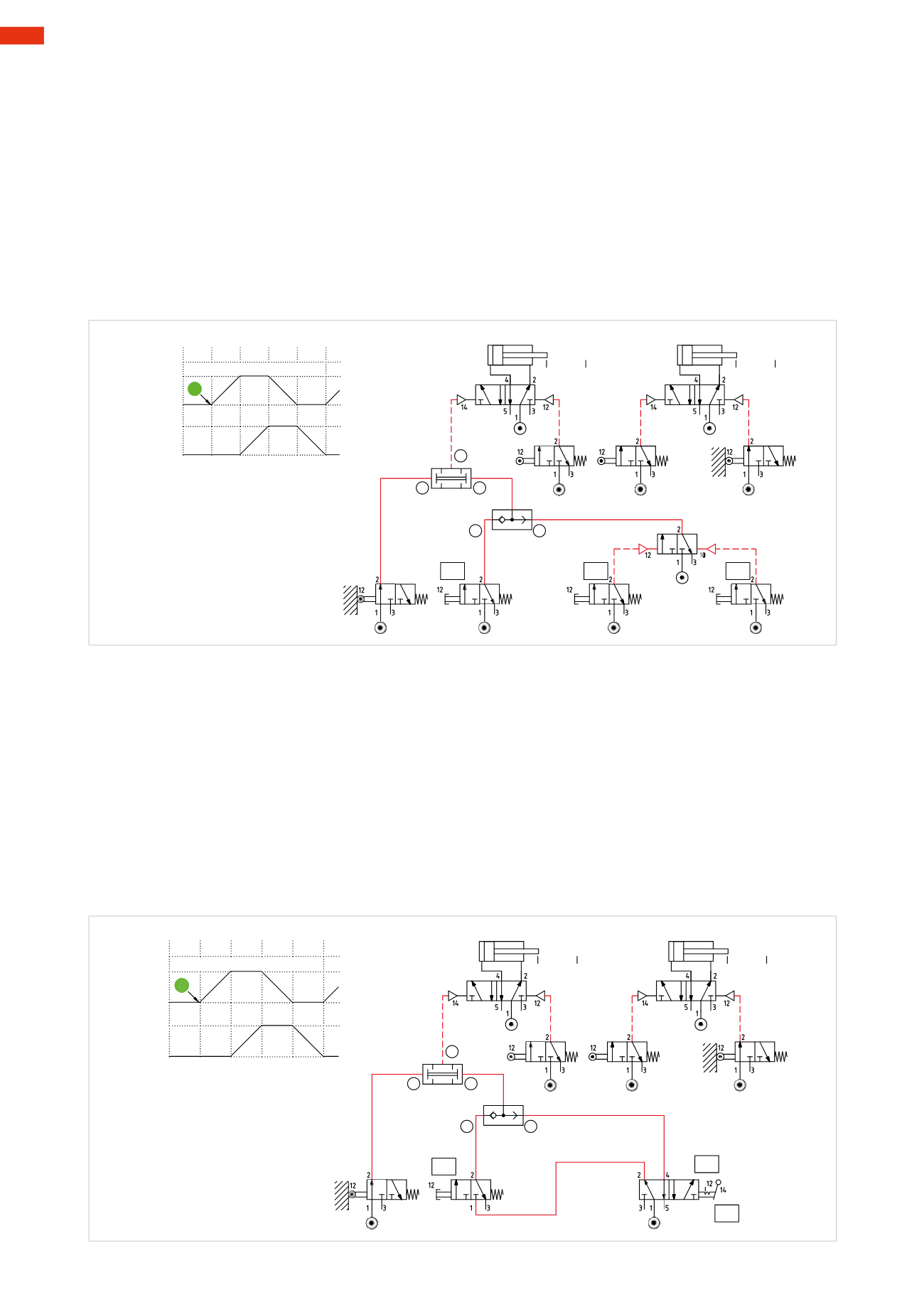
Single/continuous cycle
As previously analyzed, a cycle can be single or continuous; this functionality can be implemented withmultiple
circuit solutions.
Figure 58
Single cycle
: the compressed air feeds the
C.S.
(ciclo singolo)(single cycle) button, when activated, the signal “
a
”
is forwarded to the
OR
and continues to the
AND
. In the presence of signal “
b
” generated by the switch
b0
, output
X
, which becomes the start signal, is obtained. The cycle requires the activation of the
C.S.
button to restart.
Automatic cycle
: by pressing the
I.C.
button, an output signal is generatedwhich operates thememory valve, this
changes over and sends signal “
b
” to the
OR
and continues to the
AND
. In the presence of signal “
b
” generated
by the limit switch
b0
, output
X
which becomes the start signal, is obtained.
Thecyclecontinues to repeat itself as longas theEndCycle (
F.C.
) command remainsnon-actuated, as it repositions
thememory valve to the closed position.
_A
+
B_
+
1 2 3
1 4
I.C.
b0
a0
a1
a1
A
B
a0 a1
b1
X
a1
a0
b0 b1
b
b
a
a
b0
C.S.
I.C.
F.C.
Fig. 58
Figure 59
The cycle is the same, with the exception of the beginning of the cycle- in particular the start signal. A bistable
manual 5/2-way valve representing the functions
C.S.
(Single cycle) and
C.A.
(Automatic Cycle), have replaced
the
I.C.
,
F.C.
andmemory valves.
5/2-way valve in the Single Cycle C.S. position
The
C.S.
button is fedwith compressedair by the5/2way valve, though in the closedposition, signal “
a
”, if operated,
is forwarded to the
OR
and continues to the
AND
. In the presence of signal “
b
” generated by the switch
b0
, output
X
which becomes the start signal is obtained. The cycle requires the activation of the
C.S.
button to restart.
5/2-way valve in the Automatic Cycle C.A. position
Compressed air is fed to the 5/2-way valve and generates signal “
b
” which passes through the
OR
and afferwards
signal “
a
” to the
AND
. In the presence of signal “
b
” generated by the switch
b0
, output
X
which becomes the start
signal, is obtained. If the 5/2-way valve (
C.S.
/
A.C.
) is reverted to Single Cycle, the sequence stops once the last
phase is completed.
5
162
CAMOZZI
>
CIRCUIT TECHNIQUE