


 157 / 218

CIRCUIT TECHNIQUE
Use of logic functions YES andNOT
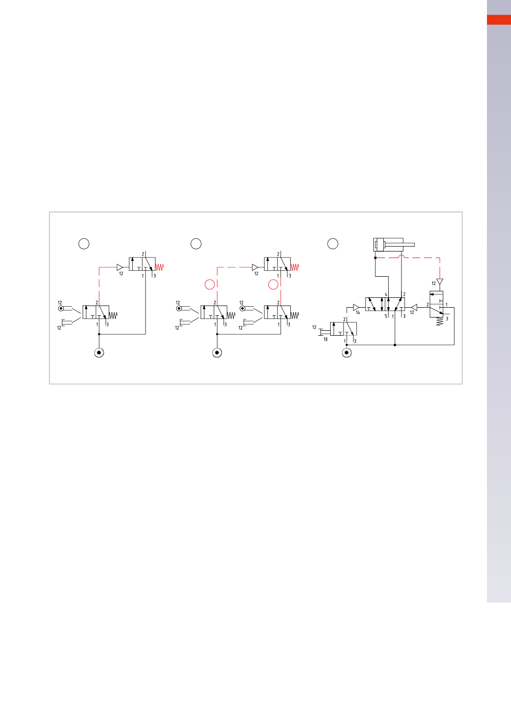
Figure 44
YES function
Pos. 1
: we have a pneumatically operated monostable
3/2-way NC
valve requiring low pilot pressure. It can be
used to amplify the pilot signal.
Pos. 2
:
the
YES
component, connected to the two valves functions as
AND
. By activating the valves manually,
mechanically or otherwise, signals “
a
” and “
b
” are generated and connected to the inlet 1 and pilot port 12 of
YES
.With the presence of both signals the output is obtained.
Pos. 3
: with the main valve in this position, the rear chamber of the cylinder is exhausted and there is no pilot
signal on the
YES
, its outlet “
a
” is not pressurized. Also themanual valvewhich is in rest position has no outlet.
In this condition the logic equation is: if
a
=
0
then
X
=
0
With the activation of themanual valve, themain valve changes over causing the cylinder to complete the positive
stroke and transmitting the pilot signal to the
YES
valve. Its outlet 2, feeding only pilot port 12 of themain valve,
does not change status as long as the manual valve remains activated. When the manual valve is released, the
cylinder will reverse its stroke, regardless of the position of the cylinder at that moment.
1
2
3
a
b
Fig. 44
Figure 45
NOT Function
Pos. 1
: we have a small-dimensioned pneumatically operated monostable
3/2-way NO
valve. The low pressure
pilot required for activationmay be used to control the pressure inside the chamber.
The logic equation is: if
a
=
0
then
X
=
1
Pos. 2
: inversion of the signal coming from an
AND
element
The
AND
element generates an output in the presence of its two pilot signals, it is possible to create a
NAND
function (Negated
AND
) by connecting the output of the
AND
to the
NOT
.
Presuming the output of the function
AND
towards the
NOT
is active, then
X
=
0
.
Signal inversion coming from an
OR
component.
The
OR
element generates an output signal in the presence of at least one of its two pilot ports, it is possible to
create a
NOR
function (Negated
OR
) by connecting the output of the
OR
to the pilot port of the
NOT
.
As long as the output of the function
OR
towards the
NOT
is active,
X
=
0
.
In both cases, the logic equation is: if
a
=
1
then
X
=
0
Pos. 3
: use of the
NOT
function as a limit switch.
By activating themanual valve, themain valve changes over and the supply of the cylinder chambers is reversed.
The pilot port of the
NOT
function continues tobe fedby theair pressure exhausted from the cylinder, and theNOT
remains piloted until the pressure in the exhaust reaches theminimum value for the pilot signals (about 0.2
bar
).
When the pressure reaches this value, we have: if
a
=
0
then
X
=
1
The output
X
of the
NOT
function is connected to pilot port 12 of the 5/2-way valve, and it has a momentary
effect, in fact immediately after the valve changeover, outlet 2 is again pressurized, restoring the condition: if
a
=
1
then
X
=
0
Themanual valve is now ready for a new operation.
5
155
CAMOZZI
>
CIRCUIT TECHNIQUE