


 156 / 218

The condition can also bewritten in the followingway:
“
a
”
AND
, “
b
”
AND
, “
c
”
AND
“
d
”
or
“
e
” then the logic equation
X
is as follows:
X= a * b * c * (d+ e)
The parenthesis encompassing the information“
d
”, “
e
” in the equation, signify that in the presence of the
AND
of “
a
”
*
“
b
”
*
“
c
”, only
d
) or
e
) are necessary to start the cycle. Once the problem has been translated into a logical form,
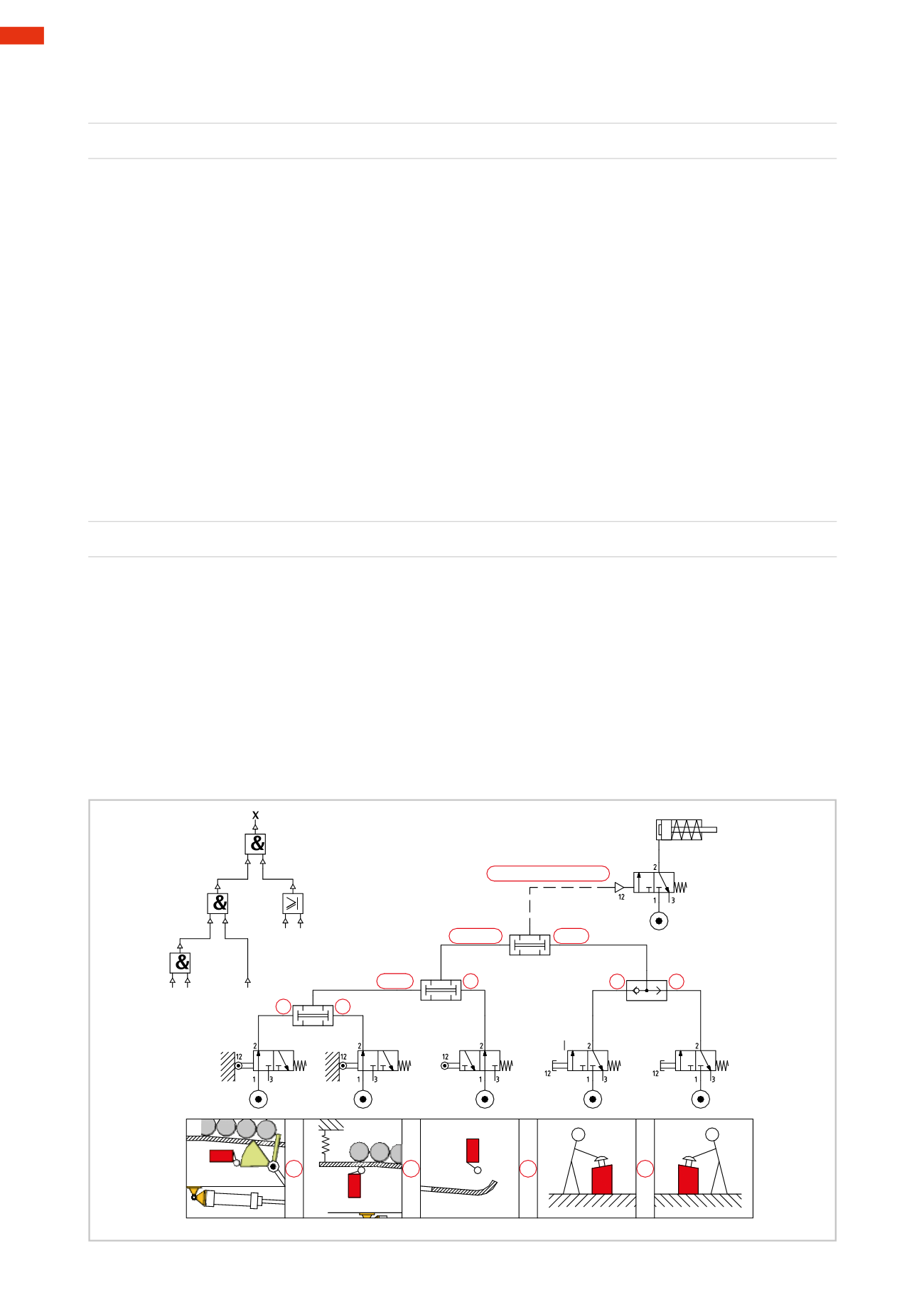
we analyze the procedure for the preparation of the pneumatic circuit:
Figure 43
Type of limit valves (switches):
information “
a
”
the separator has uploaded a bar.
This limit switch is activated by the position of the separator.
Herewe use a
3/2-way NC
valvewhich, when
activated
, has outlet with status
1
information “
b
”
at least one bar is present in the stock.
This limit switch is activated by the presence of the bar.
Herewe use a
3/2-way NC
valvewhich, when
activated
, has outlet with status
1
information “
c
”
there are no bars on the discharge area.
This limit switch need not be activated andmust be confirmed to not be so.
Herewe use a
3/2-way NO
valvewhich, when
not activated
, has outlet with status
1
information “
d
”
,
“
e
” herewe usemanually operated
3/2-wayNC
valveswhich, when
not activated
have the outlets
with status
0
Information path of the limit switches:
The initial condition required in order to activate the device is given by the equation:
a * b * c
One solution is to connect the three valves in “series”, i.e. to feed only the first with compressed air; the outlet of
thiswill feed the secondwhose outlet will feed the third. The same function can be obtainedwith the
AND
element
whichhas only twopilot ports,while in this case three signals are required, therefore two
AND
elements areneeded.
The path of the two control signals:
The signals “
d
”; “
e
”can be generated by two separate 3/2-way NC valves, both separated from each another, but
equally capable of enabling the start of the cycle. The destination of these two signals is the same so theymust be
united into a single logical element, permitting at least one of the two input signals to continue. The suitable logic
element for this function is the
OR
element.
Unification of the two signal groups:
with
(
d+ e
):
Theoutput signal
X
from the logical equation (
a * b * c
)must be in
AND
with theoutput signal
X
in the logical equation
(
d+ e
), the final output
X
controls themain valvewhich in turn activates the outwardmovement of the cylinder.
a * b * c (d+e) =X
a * b * c
d+ e
a * b
c
d
e
a
b
a
b
c
d
e
a
b
c
d
e
*
*
*
+
a b
c
d e
Fig. 43
5
154
CAMOZZI
>
CIRCUIT TECHNIQUE