


 163 / 218

CIRCUIT TECHNIQUE
Figure 57
Pos. 1
: with the introduction of anAND valve, the two previous valves can be powered directly from the network.
The
a0
valve is actuated and there is always a signal on the AND valve, the Start outlet is only active if the
I.C.
valve is actuated. The cycle is a single cycle.
Pos. 2
: the same connectionas the example inPos. 1with the introduction of twomonostable3/2-wayNC valves,
which allow the separation of the Start Cycle
I.C.
and End cycle
F.C.
, commands.
This condition requires the introduction of a double pneumatically operated bistable 3/2-way valve tomemorize
the signals from the two control valves.
Cycle start command
In a machine/plant, the sequence may be executed with both a
single
or semi-automatic cycle in addition to a
continuous
or
automatic
cycle. In both cases it is necessary for the start command to be given by a Start Cycle
(
I.C.
) (InizioCiclo) valve. In a
single
cycle the commandmust be repeated each time the sequence restarts. In this
case the valve that generates the start signal is a monostable valve. In a
continuous
cycle the command is only
given at the start. In this case the valve that generates the start signal is a bistable valve.
In the continuous cycle the Start Cycle (
I.C.
) valve in the actuated positionmust be connected in series with the
last signal to have confirmed the correct position of the actuators at the end of the sequence. When this valve is
deactivated (i.e. no passage between inlet 1 and outlet 2), there is no continuous cycle and the start signal cannot
restart the sequence.
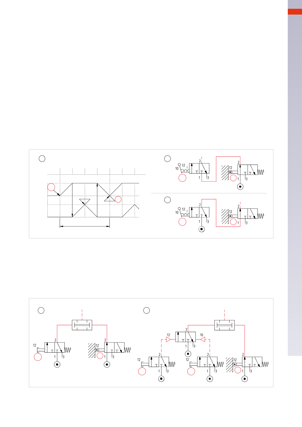
Figure 56
Pos. 1
:
as the flow chart indicates, Phase 4 is the final phase, during this Phase
a0
is the last limit switch to be
activated.
Pos. 2
:
the outlet of valve
a0
, i.e. the last signal to have confirmed the correct position of the actuators at the
end of the sequence, feeds the
I.C.
valve, which in turn permits the passage of the signal although only if it is in
C.C.
(Continuous Cycle) position. In the position shown below the valve is closed indicating it is in the
F.C.
(End
of Cycle) position. In the case of amonostable
I.C.
valve, the cyclewould be a single cycle andwould need to be
operated at each sequence end.
Pos. 3
:
contrary to the previous situation, the
I.C.
valve is fed by the compressed air. It is only possible to generate
the Start commandwhen both the
I.C.
valve and the limit switch
a0
are operated.
1
2
3
+
_
A
+
_
B
cycle
3
1 2
4 1 2 3
a1
b0
b1
I.C.
a0
I.C.
I.C.
a0
a0
Fig. 56
The Start function can be achieved with manual monostable valves and manual bistable valves. The choice
remains with the designer of the circuit to adopt themost adequate solution for the application involved.
Start
Start
I.C.
I.C.
F.C.
a0
a0
1
2
Fig. 57
5
161
CAMOZZI
>
CIRCUIT TECHNIQUE