


 162 / 218

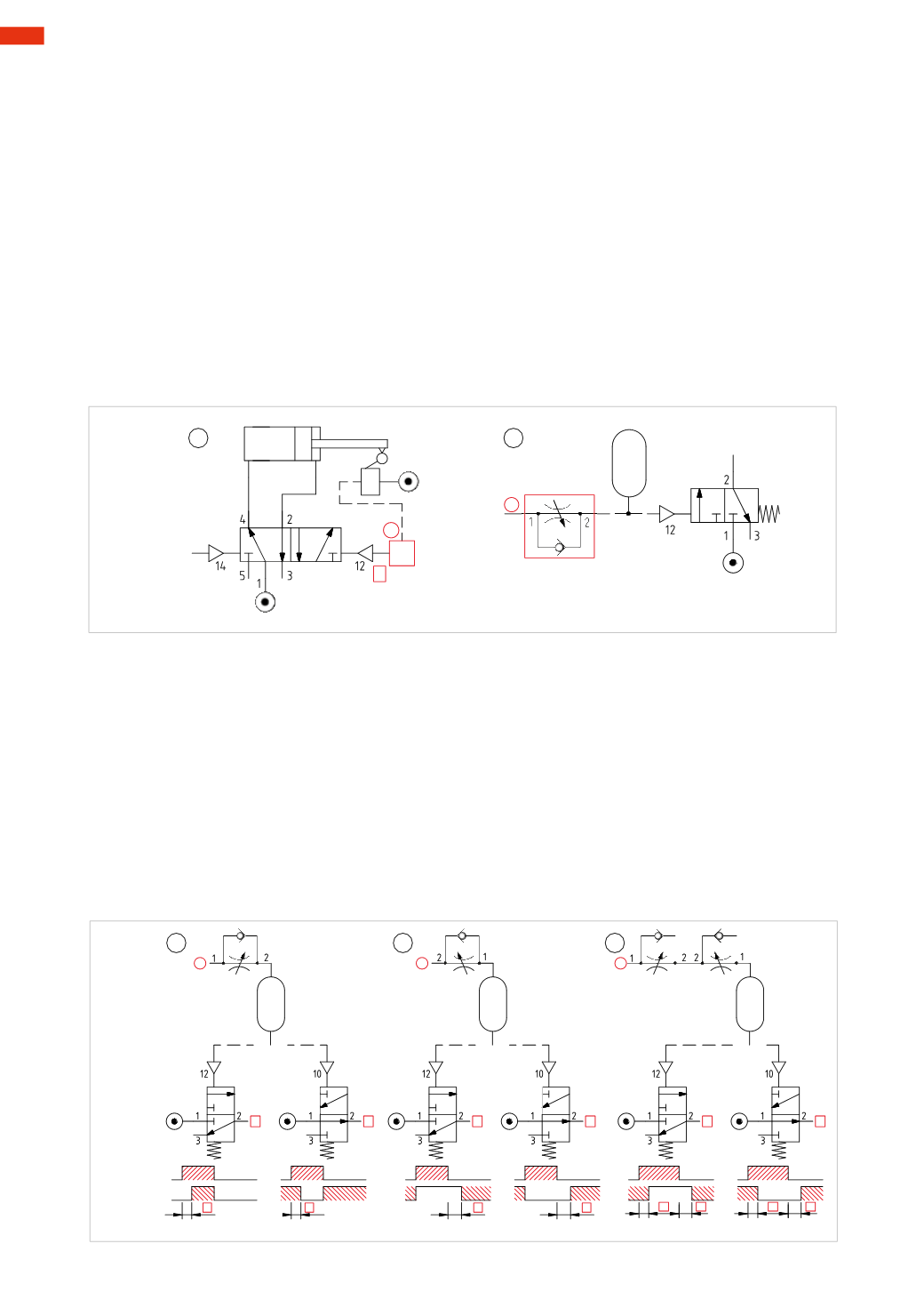
The timer
The function of the timer is to regulate the duration of a signal.
Figure 54
Pos. 1
: when the cylinder activates the limit switch, both the output “
a
” and the changeover of themain valve for
subsequent movement are immediate. A timer is installed if the cylinder is required to remain at the end position
for a given amount of time before returning. This timer sends an output “
x
” once the required time has passed.
Pos. 2
:
a timermay be “constructed” by connecting pneumatic components.
A unidirectional flow regulator
regulates the amount of air inside a circuit, which comprises a reservoir and the
pilot port of a 3/2 valve. The regulator can be connected in twomodes; to regulate the “
input
” or the “
exhaust
”;
this will delay the actuation of the 3/2-way valve or keep it actuated for a certain amount of time after the signal
“
a
” has been discontinued.
The regulation of the flow control valve: the less air that is allowed to pass (smaller flow), the longer it takes for
the reservoir to fill and actuate/release the valve.
A capacity/reservoir
: the larger its volume, the greater the time “
t
” needed to fill or empty it through the reduced
cross section created by the flow regulator, whereby the internal pressure reaches the value required to actuate/
release the valve.
A3/2-way valve
: NC or NO depending on the type of function requested by the timer.
X
X
1
2
a
a
Fig. 54
Figure 55
Pos. 1
:
delaying of signal “
a
”.
The reservoir is filled slowly as the flow regulator is reducing the flow. The valve is actuatedwith a delay “
t
” after
the arrival of the signal “
a
” regardless of whether it may be a
3/2-way NC
or
3/2-way NO
.
Pos. 2
: maintaining signal “
a
” after its interruption.
The reservoir is slowly exhaustedas the flow regulator reduces the flow; signal “
a
” ismaintained for a certainamount
of time after its interruption. The valve returns with a delay “
t
” after the interruption of the signal “
a
”, regardless of
whether it is a
3/2-wayNC
or
3/2-wayNO
.
Pos. 3
:
a combination of the above.
There are two different delays, one during the filling phase and one during the exhaust phase of the reservoir.
When signal “
a
” arrives, the reservoir fills slowly, as the flow regulator at the inlet is reducing the flow, delaying the
actuation of the valve by time “
t
1
”.When signal “
a
” is interrupted, the reservoir slowly empties as the exhausting
flow regulator is reducing the flow; the valve remains actuated also in the absence of signal “
a
” for designated
time, “
t
2
“.
X
X
X
X
X
X
1
2
3
a
a
x
x
x
x
x
x
a
a
a
a
a
a
a
t
1
t
2
t
1
t
2
t
t
t
t
Fig. 55
5
160
CAMOZZI
>
CIRCUIT TECHNIQUE