


 165 / 218

CIRCUIT TECHNIQUE
A
B
a0
a1
b1
a1
a0
b0
b1
b0
I.C.
F.C.
EM.
_A
+
B_
+
1 2 3
1 4
I.C.
b0
a0
a1
a1
Fig. 60
Emergency command
An Emergency situation usually refers to any unforeseen and potentially dangerous situation, which requires
immediate action to ensure the safety of themachine operators.
This command can be divided into the following:
Stop during cycle
for example, either interrupting the movement of the piston rod/piston which then remains at
the position which it has reached, or allowing it to reach the end position thereby preventing the continuation of
the cycle.
General Stop
there is no specific rule for this type of stop. The system designer will select the most suitable
parameters, i.e. repositioning thepiston rod/pistonof the various cylinders to their respective initial positions, allow
them to reach the end position of pneumatically feed some areas of the plant or exhaust it partially, completely,
or vice versa.
The emergency command
EM
must be both accessible and visible. Comprised of a 3/2-wayNC valve, the actuating
device generally requires:
• a large contact surface for ease of operation (mushroom button),
• highly visible colour (red),
• a mechanical self - latching mechanism constructed so the cycle will only resume once the operator confirms
adequate safety requirements have been re-established.
Figure 60
Stop during cycle and restart from the same phase
The emergency stop EM valve is connected to the pilot port of a monostable 3/2-way NO valve that provides
compressed air to all limit switches. In the presence of this pilot signal from theEM valve, the3/2-way valve shuts
off the passage interrupting the air supply to the limit switches preventing the continuation of the cycle.
The piston rod/piston of the cylinder stops upon reaching the end position. When the air supply is restored to the
limit switches, the sequence resumes from its stopped position.
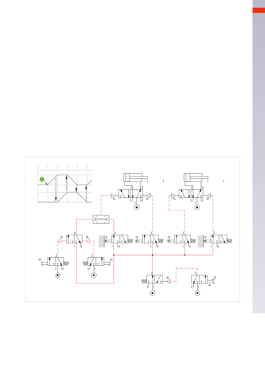
Figure 61
A variation of the previous condition
The EM valve is connected to the pilot port of a pneumatically operatedmonostable 5/2-way valve, which, in rest
position, feeds the limit switches and the 3/2-way valve thus enabling the sequence.
When the EM valve is actuated, the pressure supply of the limit switches is interrupted, preventing the continuation
of the cycle, as in the previous example. Upon resetting the EM valve, the cycle restarts from the phase where it
was interrupted as in the previous case. With this variation, one can decide whether to resume from the stopped
position, or re-start from the first phase by pushing the
RESET
button.
When the EM valve is actuated, the
RESET
valve is fedwith compressed air and as a result of its operation using
the
OR
functions, it is possible to return the piston rod/piston of the actuators to their respective starting position.
5
163
CAMOZZI
>
CIRCUIT TECHNIQUE