


 168 / 218

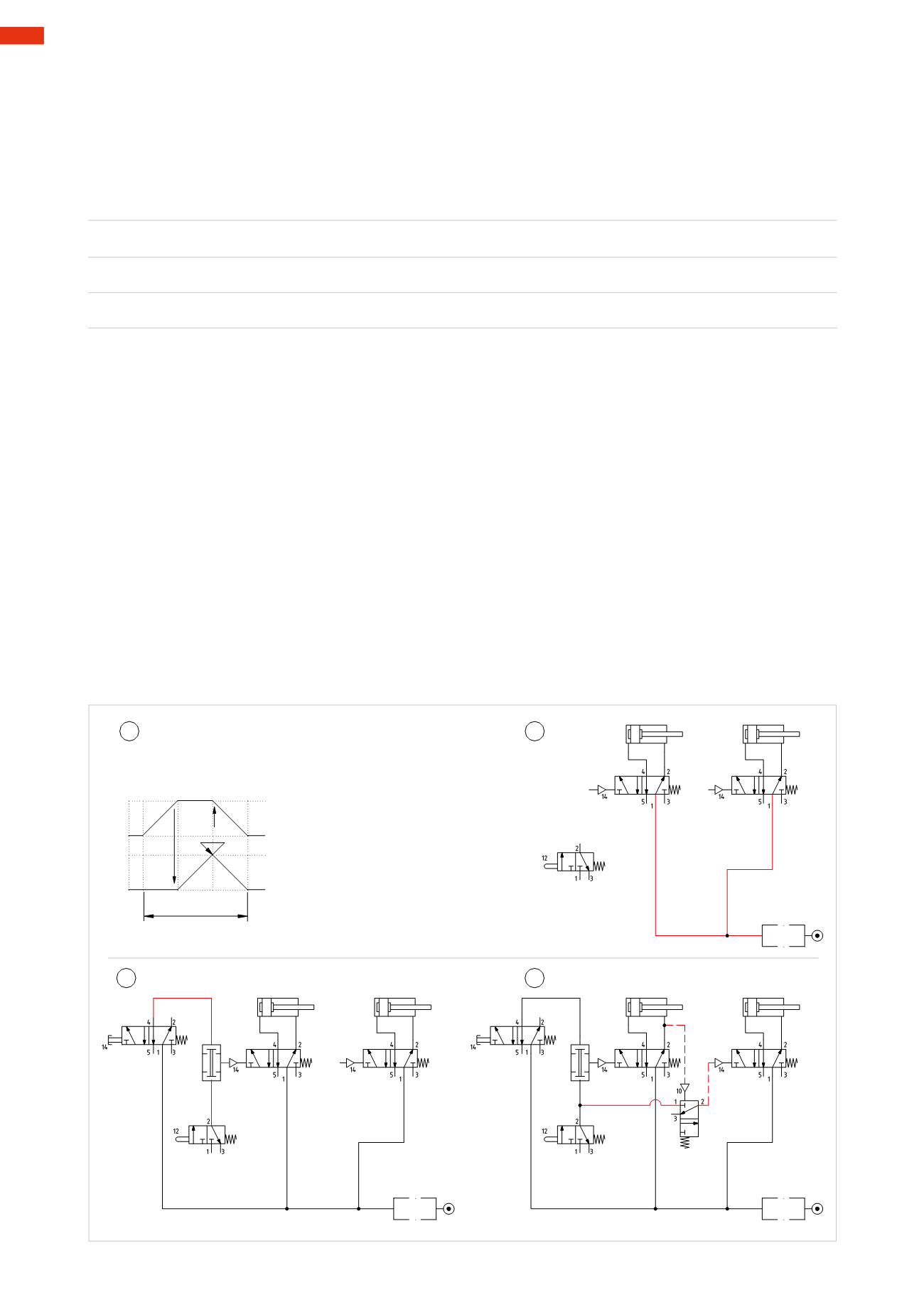
Flow diagram and designing a pneumatic circuit
A flow diagram based on the literal description of the sequence, can be constructed once the cycle and the safety
conditions are established.
S
represents the valvewhich detects the closure of the safety door and
I.C.
represents
the Start Cycle.
Figure 64
Pos. 1
: the cycle takes place in three Phases:
Phase 1
I.C. * S=
A+
Phase 2
I.C. * S * a1=
B+
Phase 3
I.C. * S * a1 * b1=
A – B –
Pos. 2
: the safety conditions indicated in the previous paragraph require that in the absence of the
I.C.
command
or opening of the safety door, the piston rod/piston of the cylinders should return to their initial position.
The easiest way to achieve this is to control the two cylinders with monostable 5/2-way valves, which r in the
absenceof thepilot signal, are repositioned, inverting theoutlets guaranteeing the required conditions. The strokes
of the two cylinders are variable, as the dimensions of the component are not defined, therefore it is not possible to
use limit switches. Todetect thepositionof the cylinders, logical
NOT
elements areused. As commonpractice, the
valves and cylinders are represented in the circuit in the positions they assume in rest condition. The connection
of the twomonostable 5/2-way valves to the network ensure that in the absence of the pilot signal, the piston rod/
piston of both cylinders are at the negative end position. Valve
S
is not connected at thismoment.
Pos. 3
: positive stroke of the piston rod/piston of the cylinder
A
. The safety prerequisite necessary to start the
cycle requires the presence of the signal coming from both the
I.C.
valve and the
S
valve. In order to satisfy this
condition, we introduce the logical
AND
function, whose output, determined by the presence of the two inputs
(
I.C.
and
S
), operates the main valve of cylinder
A
. The
I.C.
valve is a monostable 5/2-way valve operated by a
button fed directly from the compressed air network and outlet 4which is inactive and connected to the inlet of
the
AND
element. The limit switch
S
is amechanically operated 3/2-way valve NCwhose outlet 2 is connected
to the other inlet of the
AND
element.
Pos. 4
: introduction of the logical function
NOT
for stroke
A+
. The
NOT
function receives the pilot signal only
when the cylinder
A
has almost completely exhausted the compressed air from the front chamber confirming that
it has terminated its stroke against the component. The output of theNOT
a1
is connected to pilot port 14 of the
main valve of cylinder
B
which through its changeover allows the positive stroke.
B
-
cycle
-
+
A
+
1 2
a1
b1
3 1
I.C. * S=A+
I.C. * S * a1=B+
I.C. * S * a1 * b1=A-B-
Cil. "A"
Cil. "B"
S
Cil. "A"
Cil. "B"
I.C.
S
Cil. "A"
Cil. "B"
I.C.
S
a1
1
2
4
3
Fig. 64
5
166
CAMOZZI
>
CIRCUIT TECHNIQUE