


 199 / 218

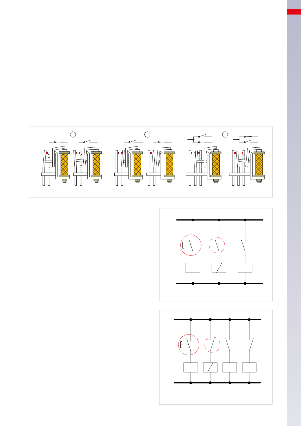
ELECTRO-PNEUMATIC CIRCUITS
Relay circuits
A relay is an electric component combined with one or more contacts, also with different functions. These are operated
by means of a mechanism activated by a coil, changes its state, by either opening or blocking the passage.
Figure 2
Pos. 1:
A
: the coil is de-energized the contact is
NC
and the electrical signal can pass;
B
: the coil is energized and attracts the moving mechanism, which opens the contact. The electric signal can no
longer pass.
Pos. 2:
A
: the coil is de-energized, the contact is
NO
and the electrical signal does not pass;
B
: the coil is energized and attracts the moving mechanism, which closes the contact. The electrical signal can
now pass.
Pos. 3:
in this case the relay has two contacts with different functions: one
NO
and one
NC
A
: the coil is de-energized, the electrical signal can only pass through the
NC
contact
B
: the coil is energized and attracts the moving mechanism inverting the status of the contacts. The
NO
contact
closes and the electrical signal can now pass, as the
NC
contact opens the electrical signal is interrupted.
1
2
3
A
B
A
B
A
B
Fig. 2
Figure 3
Identity Function
Line 1:
the
P1
button is connected to an
NO
contact.
The output signal energizes the coil of relay
X
which is
connected to the two
NO
contacts,
x
and
x
1
.
Line 2:
contact
x
of relay
X
is connected, the output
signal energizes coil
B1
.
Line 3:
the contact
x
1
of the relay
X
is connected, this
contact has no applied load.
In the circuit diagram illustrated below, closing contact
button
P1
results in:
• the relay
X
energizes
• contacts
x
and
x
1
on
Lines 2
and
3
close
• At each activation of
P1
, the coil
B1
is energized
Figure 4
Negation Function (inverter)
Line 1:
the
P1
button is connected to an
NO
contact.
The output signal energizes the coil of relay
Y
which
has two
NC
contacts,
y
and
y
2
,
and one
NO
contact,
y
1
.
Line 2:
contact
y
of relay
Y
is connected, the output
signal energizes coil
B2
. In this phase the coil is energized.
Line 3: y
1
is connected to the contact of relay
Y
, this
contact has no applied load.
Line 4: y
2
is connected to the contact of relay
Y
, this
contact has no applied load.
In the circuit, closing contact button
P1
results in:
• the
Y
relay energizes
• contacts
y
and
y
2
open
• contact
y
1
closes
• coil
B2
is de-energized
Each activation of
P1
de-energizes coil
B2
.
NO/2-3
P1
x
x
1
X
B 1
1
2
3
Fig. 3
NO/3
NC/2-4
P1
y y
1
y
2
Y B 2
1
2
3
4
Fig. 4
6
197
CAMOZZI
>
ELECTRO-PNEUMATIC CIRCUITS