


 200 / 218

P1
P2
X
X
x
P1
x
P2
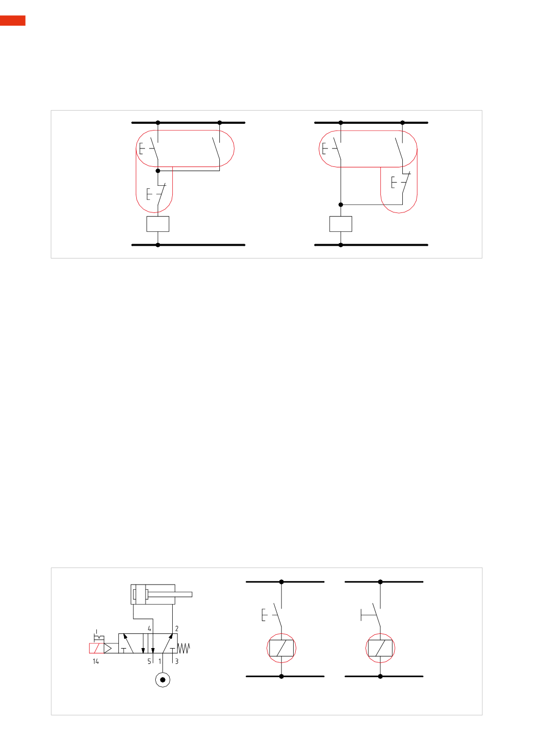
Fig. 5
Figure 5
Memory Function
It is possible to create this circuit using two different connections. By pressing briefly on push-button
P1
, the coil
of relay
X
energizes as the
P2
contact button is closed. The contact
x
closes and keeps the relay energized even
after the release of the push- button
P1
. To cancel thememory, briefly press push- button
P2
,which canbe placed
in both positions as illustrated in the drawing.
Control systems
Upon analysis of the various electrical contacts, we examine how to incorporate them into a circuit.
In our examplewe assume the contact load is a solenoid of a solenoid valve.
In this first electro-pneumatic circuit example, the push buttons directly activate the solenoids.Wewill later observe
that the commands act as Inputs on a PLC (Programmable Logic Controller), or activate the coil of a relay, they
never act directly on the load. The load is connected to the contacts of the relay.
The
power
and
control
circuits are represented in an electro-pneumatic diagram.
In the
power
circuit the pneumatic components (cylinders and solenoid valves) are represented. In the
control
circuit, traditional electrical components (relays, contactors, contacts, and also the electrical parts of pneumatic
components such as solenoids) are represented.
Figure 6
Activation of amonostable 5/2-way solenoid valve
.
A
: with the activation of the
P1
button, the
NO
contact closes, the electrical signal reaches and energizes solenoid
B1
. The solenoid valve changes over and allows the positive stroke of the piston rod/piston of the cylinder.
The duration of the activation on button
P1
corresponds to the duration of the electrical signal that energizes the
solenoid
B1
.When releasing the
P1
button, the solenoid valve returns to its rest positionand the cylinder completes
the negative stroke.
B
: the button
P1
has been replaced by selector switch
S1
which maintains the position given by the activation.
When
S1
is activated, the
NO
contact closes, the electrical signal reaches and energizes solenoid
B1
The solenoid
valve changes over and allows the positive stroke of the cylinder piston rod/piston. The negative stroke is only
possiblewhen the selector is repositioned.
P1
S1
B 1
B 1
B1
A
B
Fig. 6
6
198
CAMOZZI
>
ELECTRO-PNEUMATICCIRCUITS