


 201 / 218

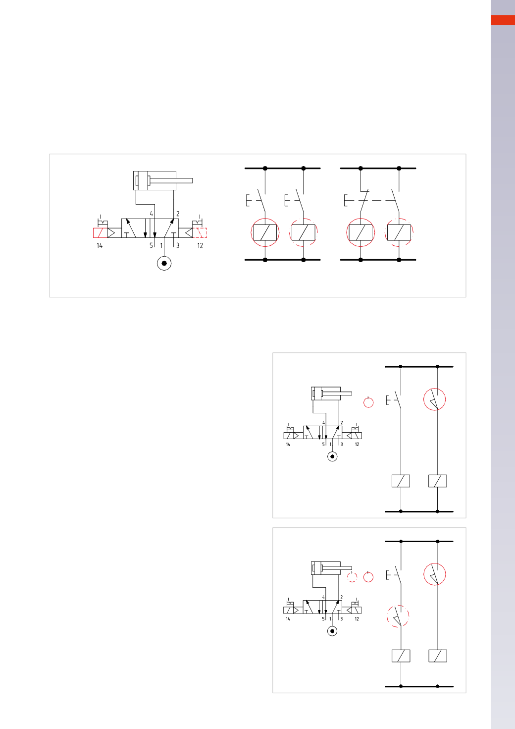
ELECTRO-PNEUMATIC CIRCUITS
Figure 7
Activation of a bistable 5/2-way solenoid valve
.
A
: buttons
P1
and
P2
, through
NO
contacts, are connected respectively to solenoids
B1
and
B2
. In this case, as
the solenoid valve is bistable, a continuous signal on the solenoids is not required. If button
P1
, is pressed, the
NO
contact closes and an electrical signal energizes solenoid
B1
and the cylinder completes the positive stroke.When
the button is released, the contact re-opens and the electrical signal is interrupted, the solenoid valve maintains
its position however, repeating the same action on button
P2
, the negative stroke completes.
B
:
P1
and
P2
have been replaced by selector
S
on which one
NC
contact and one
NO
contact are operated
simultaneously.When the
NC
contact opens, the
NO
contact closes and vice versa.
This solution, even if anomalous in the sense of thebistable function of the valve ensuring the position of the spool,
canbeanadvantage touse in thepresenceof strong vibrations that otherwise could change the status of the valve.
P1
P2
S
B 1
B 2
B 1
B 2
B1
B2
A
B
Fig. 7
The term “cycle” of a cylinder represents the period in which the piston rod/piston completes the positive and
negative strokes. The term “sequence” refers to the set of cycles of numerous cylinders necessary to perform a
given operation. Identification of: Logic lines, relays and their respective contacts.
A
a1
B1
B2
I.C.
a1
1
2
B 1
B 2
Fig. 8
Figure 8
Single cycle of a cylinder with a bistable 5/2-way
solenoid valve
.
Line 1
: through the operation of the
I.C.
button (cycle
start) the
NO
contact is closed, the signal passes and
energizes the solenoid
B1
.
The
I.C.
button can be released. The solenoid valve
changes over and the piston rod/piston completes the
positive stroke.
Line2
: thepiston rod/piston reachesandoperates limit
switch
a1
, the contact closes and energizes solenoid
B2
. The solenoid valve changes over and the piston
rod/piston completes the negative stroke.
Figure 9
Single cycle of a cylinder with detection of the initial
position, bistable 5/2-way solenoid valve.
Line 1
: through the activation of the
I.C.
button (cycle
start) the
NO
contact closes, the signal reaches the
contact of limit switch
a0
, which is then operated, as
the cylinder is in the initial position.
The signal energizes solenoid
B1
, the solenoid valve
changes over and the piston rod/piston completes the
positive stroke, the contact of limit switch
a0
is released
and returns to its
NO
state.
The
I.C.
button can be released.
Line 2
: the piston rod/piston reaches and activates
limit switch
a1
the contact closes and energizes
solenoid
B2
. The solenoid valve changes over and the
piston rod/piston completes the negative stroke.
Theprocedure is the sameas
Figure8
,where the cycle
only startsupon confirmationof the initial positionwith
the limit switch
a0
activated.
A
a1 a0
B1
B2
I.C.
a1
a0
1
2
B 1
B 2
Fig. 9
6
199
CAMOZZI
>
ELECTRO-PNEUMATICCIRCUITS