


 198 / 218

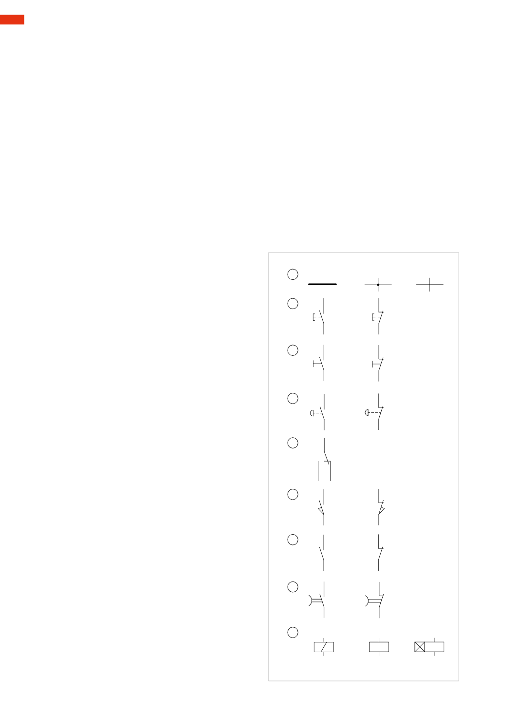
Figure 1
Pos. 1:
A
: power line
B
: connection point
C
: lines intersectingwithout connection
Pos. 2:
A
: push button commandwith an
NO
contact
B
: push button commandwith an
NC
contact
Pos. 3:
A
: selector commandwith
NO
contact
B
: selector commandwith
NC
contact
Pos. 4:
A
: emergency push button commandwith an
NO
contact
B
: emergency push button commandwith an
NC
contact
Pos. 5:
exchanging/switching contact
Pos. 6:
A
:micro switchwith
NO
contact for endpositiondetection
B
:micro switchwith
NC
contact for endpositiondetection
Pos. 7:
A
: relay with
NO
contact
B
: relaywith
NC
contact
Pos. 8:
A
: timer with
NO
contact
B
: timer with
NC
contact
Pos. 9:
A
: coil of a solenoid valve
B
: coil of a relay
C
: coil of a timer
Electrical symbols
In the pneumatic and electrical lexicon, we use definitions Normally Open andNormally Closed.
These definitions, respective of their context will vary inmeaning:
•
pneumatic
: as observed in previous paragraphs, a valve is open when air or some other fluid circulates, and
closedwhen there is no passage (flow).
•
electrical
: we use contacts instead of valves and the contacts consist of twometal parts, one of which ismobile.
When the contact is defined as “normally open”, the electrical current is unable to pass as the two conductors
are not connected. When the contact is defined as “normally closed”, the current passes through, as the two
conductors are now connected.
The contacts may have different methods of activation: manual, mechanical or electrical, and are found inmany
electrical components such as switches, push buttons, relays, contactors, timers, etc.
These elements are generally connected (electrically) via terminals or sockets.
In pneumatic circuit diagrams, the distribution network of the compressed air is indicated by a continuous line
while the operating signals are represented by a dashed line.
In electric circuit diagrams the power line is represented by two continuous thick lines, the logic lines derive from
the power lines, they are thinner and indicate various functions such as the coils of the conductors or relays, or
their contacts or loads etc.
An electric circuit diagram is read from top to bottom and from left to right. It is advisable to indicate each logic
linewith a number and identify the contact with the letter of the relay towhich it belongs.
1
2
3
4
5
6
7
A
B
C
A
B
A
B
A
B
A
B
A
B
8
9
A
B
A
B
C
Fig. 1
6
196
CAMOZZI
>
ELECTRO-PNEUMATICCIRCUITS