


 203 / 218

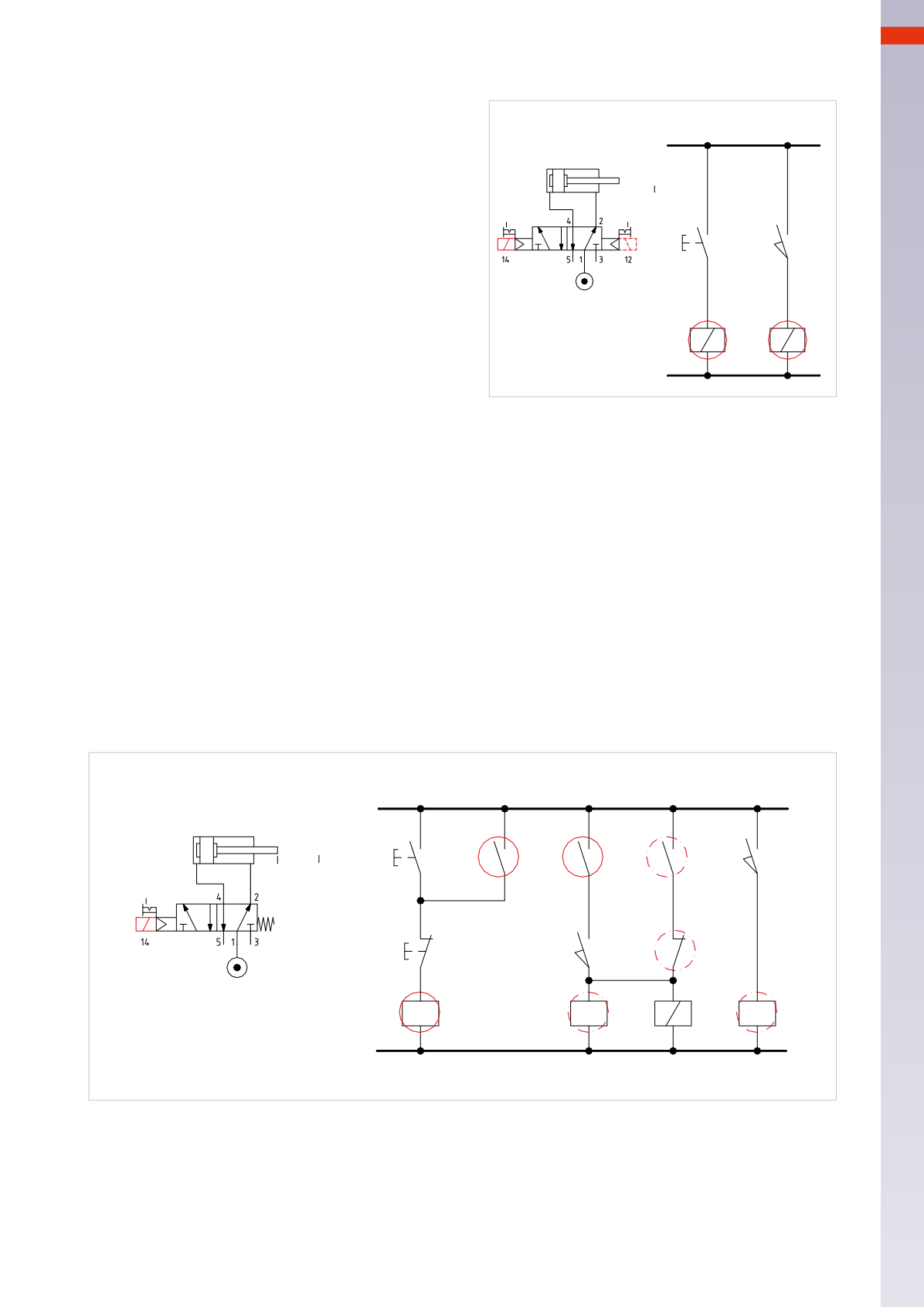
ELECTRO-PNEUMATIC CIRCUITS
Figure 12
Single cycle of a double acting cylinder with a
bistable 5/2-way solenoid valve
.
Line1:
the initial positionof the cylinder is determined
by the last received signal, in thiscase the signalwhich
energized solenoid
B2
of the solenoid valve.
When pressing the
I.C.
start button, the electric
signal reaches and energizes the solenoid
B1
.
The solenoid valve changes over and the piston rod/
piston of the cylinder completes the positive stroke.
Line 2:
once the positive end position has been
reached, limit switch
a1
is activated, the contact
closes and the electric signal energizes solenoid
B2
.
The solenoid valve repositions and the piston rod/
piston of the cylinder completes the negative stroke,
providing the
I.C.
button has been released.
Bymaintaining the
I.C.
buttonactivated, thecommand
to the solenoid
B1
blocks
B2
.
Electro-pneumatic circuit
a1
I.C.
1
2
B 1
B 2
a1
B1
B2
Fig. 12
When pressing the
F.C.
button, the coil of relay
X
no longer receives power supply:
• The piston rod/piston, carrying out its positive stroke reaches the end position then returns. When opening
contact
x
on
Lines 1
and
2
the signal to the coil of the relay is alsomaintained by
y
on
Line3
, the contact of limit
switch
a1
is not activated, and contact
z
is closed.
Once limit switch
a1
has been reached, its contact closes, the coil of the relay
Z
is then energized and contact
z
, by opening, interrupts the energizing of solenoid
B1
. The piston rod/piston returns.
•When activated during the negative stroke, the piston rod/piston stops once it has reached the final end position.
z
a1
a0
B1
I.C.
F.C.
NO/1-2
NO/3
NC/3
a1
a0
1
1
2
3
4
x
x
y
Z
1B
Y
X
Fig. 13
Figure 13
Continuous cycle of a double acting cylinder with amonostable 5/2-way solenoid valve
.
Line 1:
to obtain a continuous cyclewith amonostable solenoid valve and push button, the start command needs
to be memorized, relay
X
is added to achieve this. When pressing the
I.C.
start button, the contact closes and
the electrical signal reaches the contact of the end cycle
F.C.
button. As this contact is closed, the signal passes
through to relay
X
, energizing the coil which closes the contact
x
. The contact
x
is connected in parallel with the
I.C.
buttonwhich cannow be released. The designation
NO/1-2
below
Line1
indicates that contact
x
is open and
present on both
Line 1
and
Line 2
.
Line2:
contact
x
is closed, the contact of limit switch
a0
is closed, even thoughdisplayedas open, as it is operated
by the cylinder; the signal energizes the coil of the relay
Y
. Contact
y
closes.
Through the connection between contact
a0
and relay
Y
, the signal also arrives at
Line 3
.
The designation
NO/3
below
Line 2
indicates that contact
y
is present on
Line 3
and is open.
Line 3:
contact
y
is closed, also
z
is closed, the signal passes and energizes solenoid
B1
.
With
B1
energized, the piston rod/piston completes the positive stroke, limit switch
a0
no longer confirms the
position of the piston. To avoid the coil of the relay
Y
de-energizes when its contact opens, this signal is latched.
Line 4:
once limit switch
a1
has been reached and its contact closed, the coil of the relay
Z
is energized.
The contact
z
opens and solenoid
B1
de-energizes as it no longer receives a signal, the solenoid valve returns to
its rest position.
6
201
CAMOZZI
>
ELECTRO-PNEUMATICCIRCUITS