


 202 / 218

A
a1 a0
B1
I.C.
a1
1
2
3
B 1
a0
x
y
Y
X
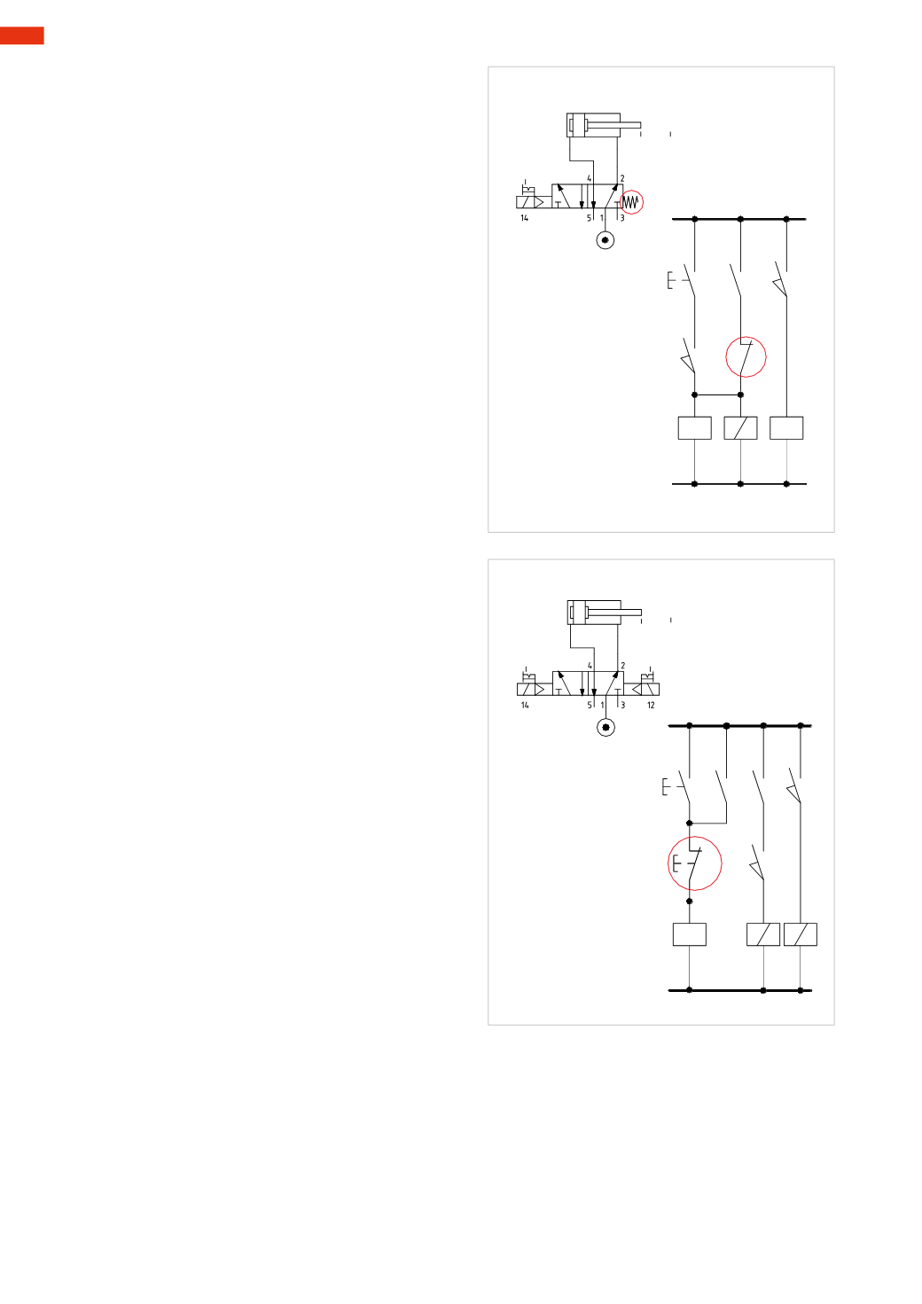
Fig. 10
Figure 10
Single cycle of a cylinder with detection of the initial
position, monostable 5/2-way solenoid valve
.
With this type of solenoid valve, the command of the
I.C.
button must be memorized for the cylinder to
complete the entire stroke.
Line 1
: by pressing the
I.C.
button in the presence of
the limit switch
a0
, the signal reaches the solenoid
B1
of the valve in addition to energizing the coil of
the relay
X
. The solenoid valve changes over and the
piston rod/piston completes the positive stroke.
The contact
a0
of the limit switch is released and
returns to the
NO
state.
Line2
: The
I.C.
buttoncanbe releasedas thecommand
to the solenoid
B1
is latched through the contact
x
of
relay
X
.
Line3
: once thepositiveendpositionhas been reached,
limit switch
a1
is activated and the contact is closed.
The signal energizes the coil of relay
Y
, which opens
the corresponding contact
y
on
Line 2
.
As solenoid
B1
is no longer energised, the solenoid
valve repositions and the piston rod/piston completes
the negative stroke.
Figure 11
Continuous cycle of a cylinder, bistable 5/2-way
solenoid valve.
A cycle is considered continuous when it repeats
automatically. Normally the position of the piston
rod/piston of the cylinders in a machine are detected
through magnetic proximity switches located on the
cylinder tube or profile.
Theamount of current that canpass through thecontact
of these sensors is limited and depends on the power
consumption of the connected load.
To avoid problems with the sensors, the load in this
case is determined by the solenoids, and this load is
applied on the contacts
x
and
y
of the respective relays
X
and
Y
.
Line1
: the solenoids of the valvearede-energized, the
button of End Cycle
F.C.
is in the
NC
position.
By pressing the
I.C.
button the signal energizes the
coil of the relay
X
.
Line 2
: the contact
x
of the relay
X
closes, latching
Line 1
, the
I.C
. button can now be released.
Line 3
: the contact
x
in addition to latching
Line 1
passes the signal to the contact of the proximity switch
a0
. In this phase, the proximity switch is operated as
the cylinder is in rest position. The signal then reaches
and energizes solenoid
B1
of the valve.
The valve changes over, the piston rod/piston executes
the positive stroke.
Line 4
: the proximity switch
a0
is no longer operated,
the piston rod/piston reaches the proximity switch
a1
.
The signal energizes solenoid
B2
. The valve, no longer
energized by solenoid
B1
, changes over, the piston
rod/piston executes the negative stroke.
A
a1 a0
B1
B2
I.C.
F.C.
a1
1 2 3 4
B 1 B 2
a0
x x
X
Fig. 11
Upon reaching start position, the proximity switch
a0
resumes operation, the coil of the relay
X
is re-energized,
the signal on
Line 3
is still active, and with the closure of the limit switch, the signal from contact
a0
energizes
solenoid
B1
The valve changes over and the cycle resumes. The
F.C.
(End of Cycle) buttonmust be activated to
terminate the cycle.
6
200
CAMOZZI
>
ELECTRO-PNEUMATICCIRCUITS