


 30 / 218

p
A
=
F
A
100
[N]
100
[N]
p
A
=2 * 10
-5
N
⁄
m
2
p
A
=
2
bar
S
A
5
[cm
2
]
5 * 10
-4
[m
2
]
We now calculate the Force
F
E
to be applied on the surface
E
in order to keep it in equilibriumwith the piston
A
.
p
E
=
F
E
F
E
=
p
E
*
S
E
2 * 10
5
[N
⁄
m
2
]
* 10
-3
[m
2
] =
200
N F
E
=
200
N
S
E
A
F
F
A
E
F
3
4
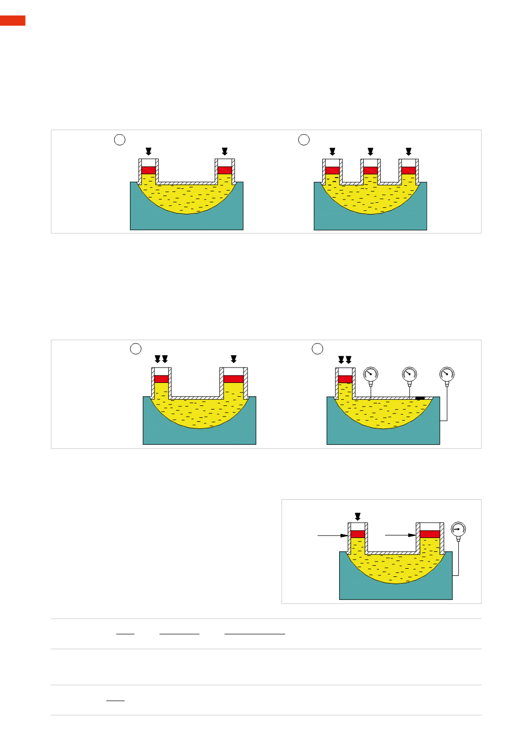
Fig. 19
Figure 19
Pos. 3
: the pistons
B
and
C
(with the same section) are now replaced by a single piston
E
whose area is the sum
of the areas
B
and
C
(
S
E
=
S
B
+
S
C
). By applying aForce
F
on only piston
A
, itwill be lowered and consequently
piston
E
rises. Maintaining the Force
F
on piston
A
and exerting the same Force
F
on piston
E
, the larger piston
E
will lower, however it will still have a higher level than
A
. Applying the Force
2F
to piston
E
will bring it into
equilibriumwith
A
.
Pos. 4
: eliminate the piston
E
and plug the tank. Introducing a pressure gauge, we note that in every point of the
metal sheet of the tank the pressure is the same.
Figure 18
Pos. 1
: a tank containing liquid is connected to the pistons
A
and
B
of equal sectionwhich exert the same Force
F
.
Regardless of the section of the tank and of themounting position, the level of the pistons is identical.
By increasing the Force
F
on one of the two pistons, the other will rise.
Pos. 2
: a third piston
C
, of equal section, is added next to
B
. Exerting a Force
F
only on piston
A
, pistons
B
and
C
will rise equally. Applying the same Force
F
on the pistons
A
and
B
, theywill achieve equilibrium, piston
C
will
move upwards. In the case in which the same Force
F
is applied to piston
C
, the three pistons will be positioned
at the same height.
F
F
A
B
F
A
B
C
F
F
1
2
Fig. 18
The explanation of the phenomena described above is illustrated in
Pascal’s principle
, which states that:
pressure
exerted anywhere in a confined incompressible fluid is transmitted equally in all directions throughout the fluid
such that the pressure ratio (initial difference) remains the same
.
Figure 20
Observe the physical effects of this principle:
Assuming that the piston
A
has a section
S
A
=5
cm
2
and the Force
F
A
=100
N
;
calculate the pressure exerted on the fluid
(1
N
/
m
2
=1
bar
= 1 * 10
-5
P
a
)
A
E
F = 100N
S =10 cm
2
E
S =5 cm
2
A
2bar
A
F =?
E
Fig. 20
1
28
CAMOZZI
>
PHYSICS