


 28 / 218

With the same procedure, we calculate the height of equilibrium
L
e
assuming
Q
B
=
120
l/min
=
2
l/s
.
ν
B
=
Q
B
=
2
[l ⁄ s]
=
2 * 10
-3
[m
3
⁄ s]
ν
B
=
20
m ⁄ s
S
1 * 10
-4
[m
2
]
1 * 10
-4
[m
2
]
2
g
*
L
e
ν
A
=
L
e
=
ν
2
A
2
g
20
2
[m ⁄ s]
2
2 * 9,81
[m ⁄ s
2
]
L
e
=
20,38
m
1
L
t
L
t
L
t
L
t
L
2
3
4
L
L
B
B
B
B
A
A
A
A
Fig. 15
Part 2
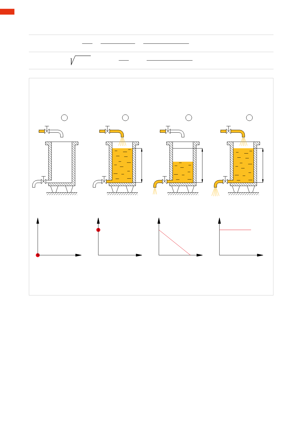
In the previous section, we observed that bymaintaining a constant input and output flow rate, the height of the
liquid in the tank ismaintained at equilibrium.
Figure 16
Pos. 1
: two pipes, with relative valve sectionswhereby
S
A
1
=
S
A
2
=
S
are connected to the tank filledwithwater
up to the level
L
.We open the valve
B
(
S
B
>
S
) and subsequently the valve
A2
.
Once the equilibrium height
L
is reached, i.e. when the quantity of incoming liquidwill be equal to the quantity of
out-flowing liquid, we position a basin for collecting the liquid at the outlet of the valve
A2
.
After a unit of time
t
we verify the height
h
of the collected liquid.
Pos. 2
: we modify the previous system by also opening the valve
A1
and collecting the liquid in two containers.
Now the time
t
to reach the level
h
in the two basins is greater than the time noted in Pos. 1 (
t
2>
t
1).
We observe that the variation of outflow is not compensated by an appropriate change in the inlet flow, resulting
in changes in the level
L1
and therefore of the pressure.
If the valve
B
had been adjusted in order tomaintain a constant level
L1
=
L
, the same pressure of Pos. 1would
have been exerted on
A1
and
A2
and the filling time of the basinwould have been
t
2=
t
1.
Pos. 3
: let us now consider a single outlet pipe
A
of section
S
A
=2
S
In the time
t
1 a quantity of water equal to the sum of the flow of the valves
A1
and
A2
flows through the valve
A
and the underlying basin is filled up to a level 2
h
.
1
26
CAMOZZI
>
PHYSICS