


 49 / 218

AIR PRODUCTION AND PREPARATION
Pressure regulator
The pressure regulator, or pressure reducer, has the task of reducing the incoming pressure to a lower outlet
pressuremaintaining it at a steady value and independent from the variations in the incoming supply pressure or
consumption.
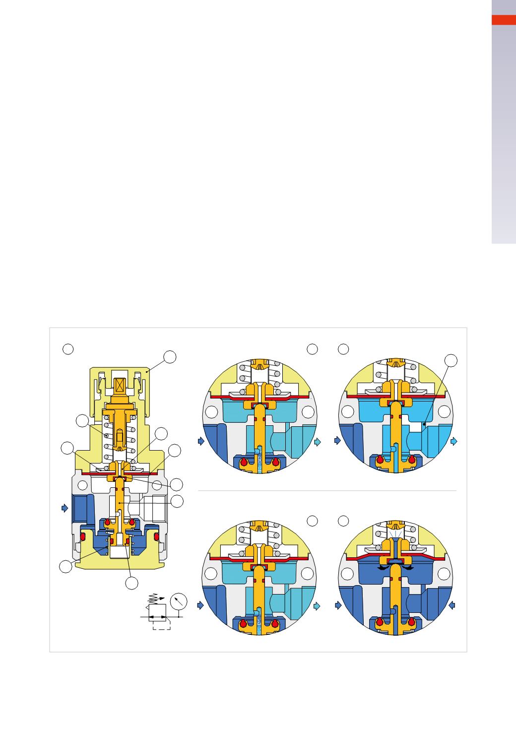
Functional principles of the regulator
Figure 15
Pos. 1
: the regulator has an incoming unregulated pressure at the inlet (from the left in blue) and is at rest position,
the spring
B
has not yet been loaded by the “knob”
A
, the disk
C
therefore is not acting on the diaphragm
D
.
Pos. 2
: represents the situation inwhich as a result of turning the knob
A
, the spring
B
becomes compressed, this
in its turn acts on the disc
C
, pushing the diaphragm
D
downwards together with the plunger
H
which opens the
poppet, enabling air to pass towards the outlet while the spring
F
is being compressed.
Pos. 3
: as a consequence of the previous phase we have a flow of compressed air proportional to the spring load
acting on the top of the diaphragm. The pressure reaches the desired value and the system returns to equilibrium.
Through the channel
L
the secondary pressure acts on the underside of the diaphragm and in this way equalizes
the force applied by the spring
B
. The plunger
H
willmoveupwards, with the help of the spring
F
andwill close the
main airflow. The system remains in this position as long as there is no consumption of compressed air.
Pos. 4
: the secondary pressure decreases as a result of the compressed air being used, the force that acts under
the membrane
D
is reduced as a result of this pressure drop, the spring
B
, whose load is constant, pushes both
the disc
C
and therefore also the diaphragm
D
downwards together with the plunger
H
which re-opens the poppet,
allowing air to pass towards the outlet.
Pos. 5
: if we encounter an overload of pressure on the secondary side (secondary pressure higher than value
adjusted by the spring
B
), this pressure reaches the underside of the diaphragm
D
through the channel
L
, lifting it
upwards. The plunger
H
, thanks to the spring
F
, closes the passage towards the outlet, the upwards deformation
of themembrane permits the opening of the channel
E
and the excess air pressure exits from the regulator through
the relieving hole
M
.
This function is called
relieving
and intervenes also in the discharge phase of the system.
The relieving function is not present on hydraulic systems.
A
B
C
E
D
H
F
G
L
M
1
2
3
4
5
Fig. 15
To improve the regulation accuracy, the regulators are availablewithdifferent springs
B
to better adapt to different
pressure ranges. The pressure regulator can be integratedwithin a single body together with a filter element.
This configuration is called the “Filter Regulator”.
2
47
CAMOZZI
>
AIRPRODUCTIONANDPREPARATION