


 52 / 218

A
B
Fig. 19
Pressure regulator without compensation
In the previous paragraphs we illustrated the operation of the traditional pressure regulator. Always using the same
pressure for all the work phases of the actuators implies an expenditure of electric energy by the compressor.
In the following paragraphs we will demonstrate that high pressure does not help to improve the speed of the piston
rod/piston in the cylinders. In fact, differentiating the pressure in the actuators accordingly between the working
and repositioning phase does not increase the cycle time, (in some cases it can even be reduced) and save energy.
When raising a load (with cylinder in a vertical position), a certain pressure which is adequate to perform this work
is required, but the same pressure is likely to inflict damage during the descent where the force of the piston is
added to the value of the load. The force of gravity by itself is sufficient to bring the load to the initial lower position.
Alternatively, another situation may arise where it may have the need to push or grip an object, in such a situation
high pressure is unnecessary in the repositioning or release phase. Some types of valve islands have two pressure
lines in order to differentiate the pressures between the working phase and the repositioning phase.
In other cases you can use pressure regulators without compensation, which are applicable between the control
valve and cylinder. A traditional regulator may not be the best solution, in fact as analyzed in the illustrations - the
pressure regulator
; a compensation chamber is visible under the plunger
A
, which is connected to the outlet of the
regulator through a small hole on the plunger. This compensation chamber allows for a better “response” i.e. better
on the traditional applications where the flow has one direction, but not ideal for applications where the regulator
is located between the valve and cylinder, (where the flow has two directions).
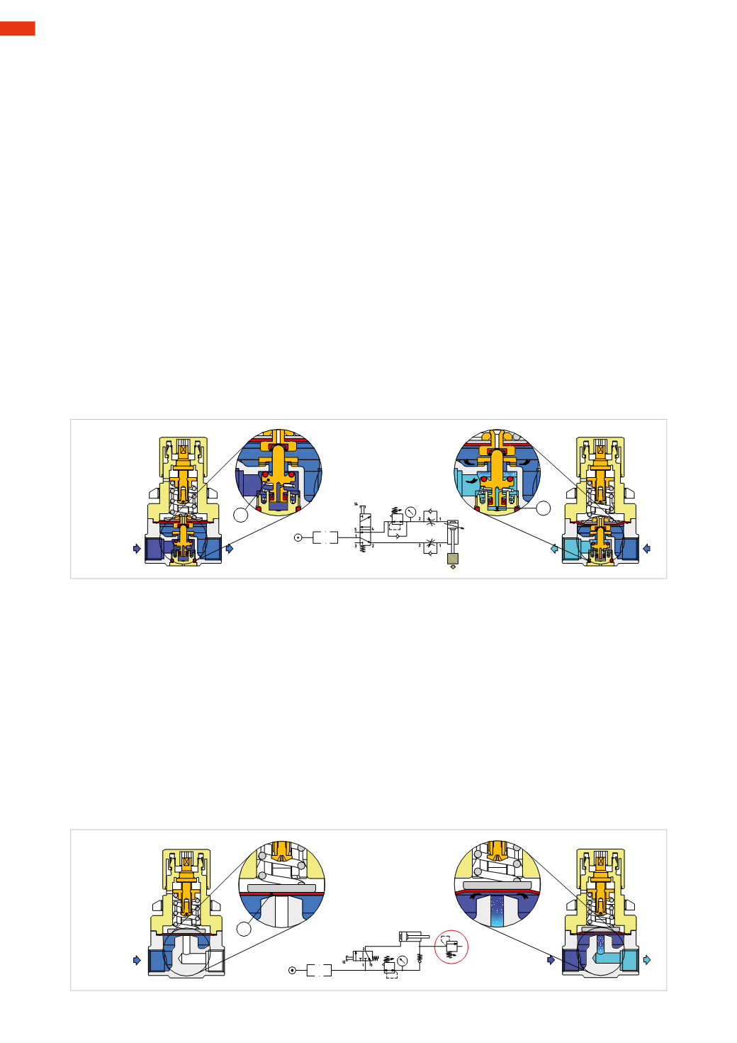
Figure 18
The regulator without compensation, the plunger
A
is different in the sense that the compensation chamber
B
uses a lip
seal and the orifice is eliminated. Removing the supply pressure, as in the application where the regulator is mounted
downstream from a directional valve, the exhaust air acts on the lip seal favouring the downward motion of the plunger
which opens the passage towards the outlet, in this way it has a higher flow rate than a traditional system. The symbol
representing this function is a standard regulator with a non-return valve.
Relief valve
In some applications you may have the need to maintain a constant pressure in a volume such as the chamber of a
cylinder that has to be constantly pressurized to a defined value. In the event of a pressure increase, the excess quantity
of air must be discharged into the atmosphere. With small volumes, as for example a small cylinder, it is possible to
connect a pressure regulator with relieving. When the volume of air to be exhausted is large, the flow characteristics of
the relieving may be insufficient.
Figure 19
This valve has the shape of a pressure regulator and it is mounted with the inlet connected to the free outlet in
connection with the atmosphere. In this way the excess pressure generated in the cylinder chamber can be exhausted
into the atmosphere. For example when we have a cylinder with the piston rod in a retracted position through a
pneumatic spring realized by a pressure regulator, where the outlet of the pressure regulator is connected to the
cylinder chamber through a non return valve (which prevents back flow through the regulator) and is branched with
a relief valve. The relief valve is adjusted at a value slightly greater than the pressure regulator so that it only opens
when there is an excess of pressure. By activating the push button the piston rod exits opposed by the pneumatic spring
force. The pressure on the negative chamber tends to increase , but is held constant by the exhaust of the relief valve.
Fig. 18
C
2
50
CAMOZZI
>
AIR PRODUCTION AND PREPARATION