


 53 / 218

AIR PRODUCTION AND PREPARATION
Treatment of compressed air: the lubricator
All modern pneumatic components are initially lubricated with highly adhesive grease, which in most cases
makes external lubrication unnecessary. Only in some situations, for example with high cylinder speeds or with
high frequency of movement of the components, further lubrication can be advantageous.
Points to consider when using the lubricator:
• Once external lubrication is applied to the components, it must not be interrupted. The oils have a cleansing
effect and remove the initial lubricating grease applied during the assembly phase of the component.
•Toensure compatibilitywith the seals, the lubricatingoil indicatedby the componentmanufacturermust beused.
• The correct quantity of oil generally ranges from1 to 5 drops every 1000 litres of air. This value should not be
exceeded.
In pneumatic systems the flow of air is used to distribute the lubricant (oil) to the components requiring it.
The device used is the “Oil Fog Lubricator”. It does so in the followingway:
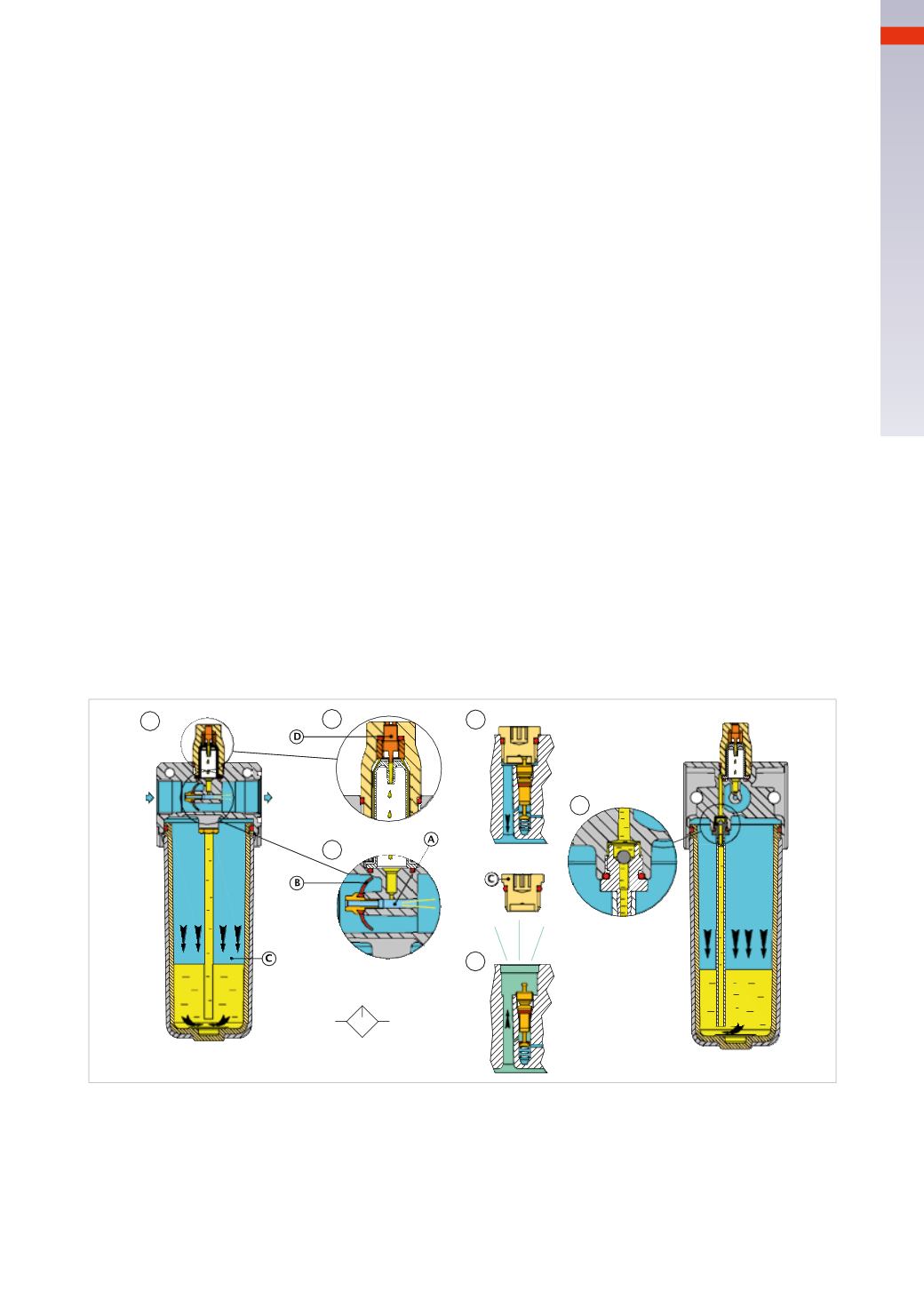
Figure 20
Pos. 1
: the incoming air of the lubricator passes both through and outside the narrow passage
A
. The incoming
pressure enters the bowl
C
containing the oil, acting on its surface, pushing it back into the tube and up to the sight
glass inPos. 2.
Pos. 2
: the adjustment screw
D
allows the regulation of the oil quantity that falls on the narrow passage.
Pos. 3
: part of thecompressedairmoving through thenarrowpassage increases its speedgenerating the
Venturi
effect
that allows the suction of the previously dosed oil.When the oil enters thenarrow passage, due to the impactwith the
high-speed airflow, it turns into an oilmist/fog, this allows it to be transported through the piping system.
The distance the oil mist flow travels depends on the amount of air required downstream and by the conformation of
the pipes. 90-degree angles, distribution collectors andall elements that could create abarrier against the air flowand
condensation of the nebulized oil are to be avoided.
Pos. 4
and
5
: thecap
C
actson thevalve inPos.5,which, beingopen, allows thepressurizationof thebowl containing
the oil. Removing the cap
C
while the system is inaction (pressurized), the valve closes theairflow to thebowl and the
remaining pressure in the bowl is released into the atmosphere. In these conditions and with
air still in the system
,
it’s possible to remove the bowl from the lubricator and refill itwith oil. Repositioning the bowl and then the cap
C
, the
bowl is re pressurized and the lubrication is resumed.
Pos. 6
: the sphere, as shown in the highlighted illustration, prevents oil from returning into the bowl each time the air
consumption stops; the oil remaining above the sphere and in the pipe is immediately available for use when the air
consumption resumes.
1
2
3
4
5
6
One potential problemwith using external lubrication is that the air, having been used in the pneumatic equipment,
is exhausted into atmosphere. This exhausted air also contains oil particles which remain suspended in the working
environment andwhichmay damage people’s respiratory systems or contaminate the finished product (critical in food
andpharmaceutical applications). It is thereforeadvisablenot toexceed thequantityof oil during lubricationandabove
all to pass the valve outlets through appropriate filters, which can reduce this effect.
If no informationon the typeof oil tobeused is provided, it isadvised touseoil for lubrication systems,whichgenerally
fall into the class ISO VG 32. Modern technology tends to limit the use of oil by producing components, which can
operatewithnon-lubricated air.
Fig. 20
2
51
CAMOZZI
>
AIRPRODUCTIONANDPREPARATION