


 47 / 218

AIR PRODUCTION AND PREPARATION
The filter
The filter element is the first part of the air treatment unit.
The impurities,whicharedepositedat thebaseof bowl
D
, canbeeliminatedbymeansof the following typesof drains.
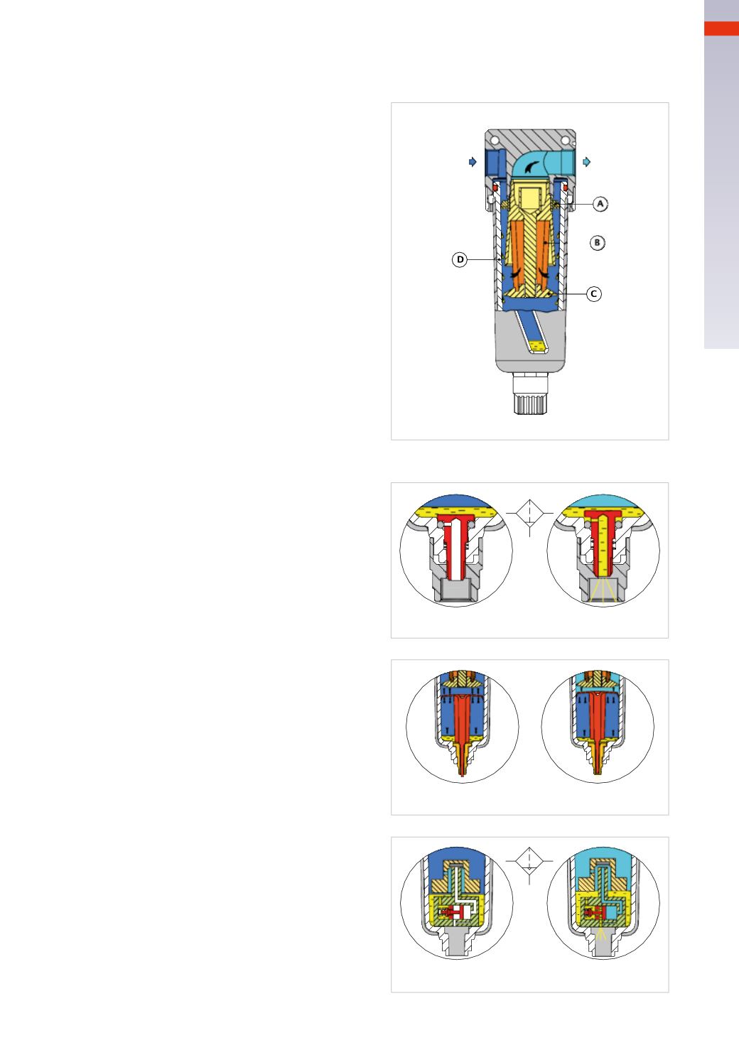
Figure 13
The condensate deposited on the base of the bowl will
rise a floater condensate that enables the opening of
thedrainage valve. As the level of liquiddecreases, the
floater closes the drainage valve.
The filtering element must be periodically cleaned
or substituted.
Figure 10
The compressed air passes into the filter inlet and
reaches the deflector
A
. This component forces the
air to swirl as it flows through the turbine type
blades. The liquid and solid particles in the airstream,
being heavier, are forced against the inner wall of
the bowl
D
as a result of the centrifugal force. The
baffle
C
separates the “turbulent” zone created by the
centrifugal effect of thedeflector, from thedeposit zone.
This prevents re-entry of the impurities into theairflow.
The liquidand solidparticlesdeposit on thebaseof the
bowl
D
. The compressed air passes through the filter
cartridge
B
, which retains the lighter impurities and
then exits through the outlet.
The filter cartridges are differentiated by the different
degree of filtering expressed in Micron (μ
m
), which
corresponds to the maximum size of the particles
to be filtered. If the filtering element is of 25 μ
m
,
means that the solid particles having a diameter
greater than or equal to 25microns will not pass, if
the filtering element is of 5 micron, solid particles
having a diameter greater than or equal to 5 μ
m
will not pass through. The characteristic of the filter
cartridge determines the class classification allocated
in the ISO table, referring to solid particles.
Fig. 10
Fig. 11
Figure 12
Automatic depressurization
The “t-shaped plate” reacts to changes in pressure
between its upper and lower side: whenever there is
anairoutflow, aslightpressuredropoccurson theupper
side allowing an upward movement for a very short
periodof time soas toallow theopeningof theexhaust
and the expulsion of impurities.
Fig. 12
Figure 11
Manual/Semiautomatic
Manual
: by turning and pushing the drainage nut
upwards its possible to open a passage from inside
the bowl towards the atmosphere. This operation is
facilitated by pressure inside the bowl.
Semiautomatic
: while pressure is applied to the
filter bowl, the outlet remains closed.When pressure
is removed the spring opens the valve, venting any
liquid in the bowl. This valve may also be operated
manually by temporarily overriding the spring.
Fig. 13
2
45
CAMOZZI
>
AIRPRODUCTIONANDPREPARATION