


 56 / 218

Principles of cylinder operation
The pneumatic cylinder is a “motor” in the sense that it is capable of converting energy into a force. The energy to
be converted is supplied in the form of compressed air (C/A).
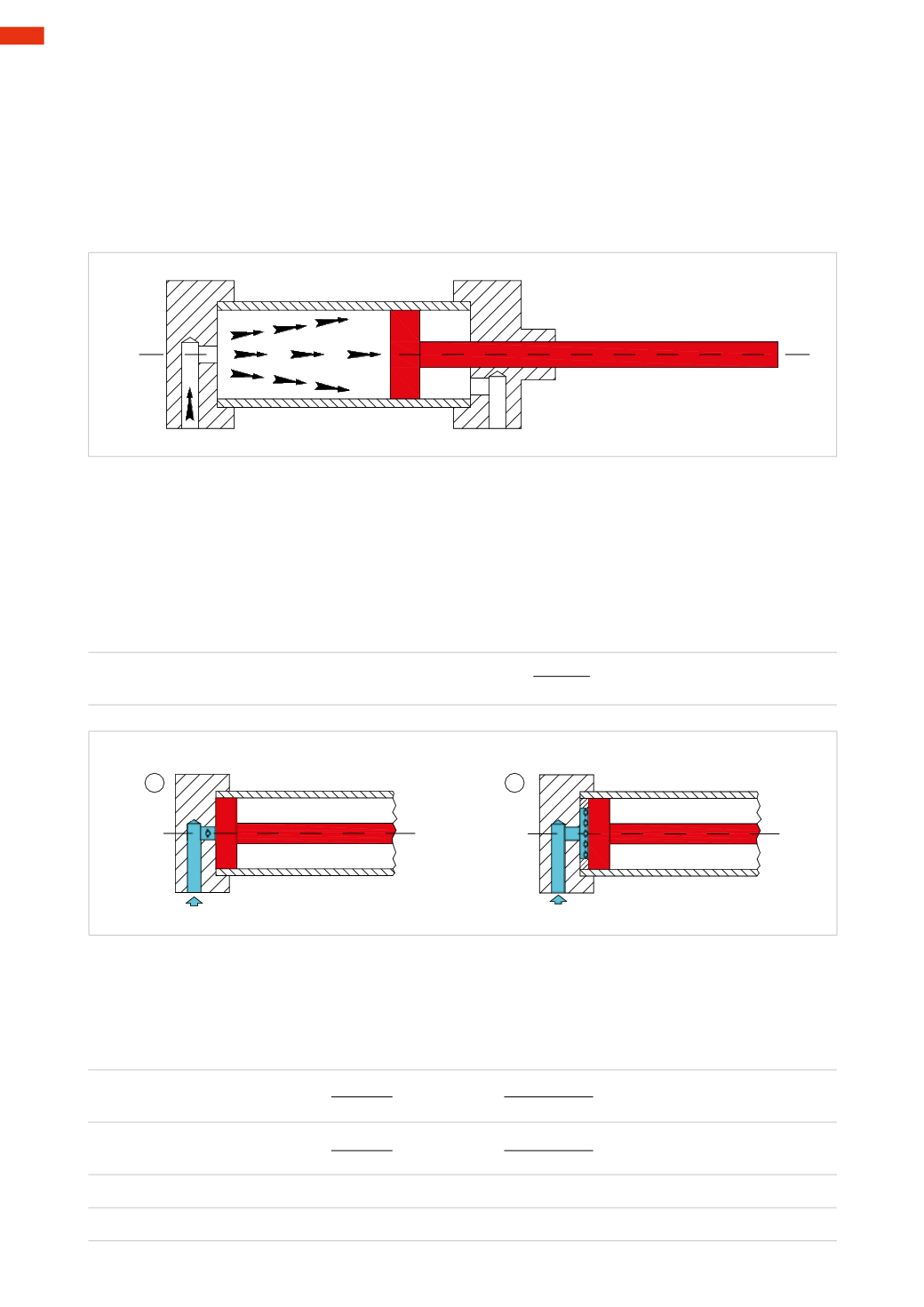
Figure 1
The principle behind this operation is the opposite to that of a bicycle pump, wheremanual effort is expended to
move thepiston therebycompressing theatmosphericair to increase thepressure in the tyre. In thecylinder however,
the pressure of the compressed air acting on the piston surface generates a force that initiates its movement, on
the condition that the air contained in the opposite chamber is able to exhaust.
Fig. 1
While air pressure is applied to one side of a piston, an effective seal is necessary to prevent air passing through to
theoppositechamber, otherwise therewill bea lossof pressureand the forcedevelopedby thepistonwill be reduced.
Figure 2
Pos. 1
and
2:
the rear surface of the piston
P
1
closes the air inlet hole. A ring separates the rear surface of the
piston
P
2
and the hole. With the same overall dimensions of the cylinder the best yield for the starting phase of
the cylinder is obtainedwith the example inPos. 2. The surface onwhich the compressed air acts ismuch greater
than that in Pos. 1.
As defined by
Pascal
’s, principle, the pistons
P
1
and
P
2
are propelled by a thrust force:
F
=
p
*
S
S
=
π
*
D
2
4
1
2
Fig. 2
Figure 3
Pos. 3
and
4:
at equal pressure, a quadratic proportionality between
S
and
F
exists, i.e. if the piston diameter
is doubled then the thrust force quadruples, if the diameter is tripled the force increases by nine times, and so
on. Given two pistons;
P
3
with diameter
D
3
= 20
cm
and
P
4
with diameter
D
4
= 10
cm
and a supply pressure
p
=5
bar
, we can calculate the thrust forces
F
3
and
F
4
:
S
3
=
π
*
D
2
3
S
3
=
3,14 * 20
2
=
314
cm
2
4
4
S
4
=
π
*
D
2
4
S
4
=
3,14 * 10
2
=
78,5
cm
2
4
4
F
3
=
p
*
S
3
F
3
= 50
[N ⁄ cm
2
]
* 314
[cm
2
]
F
3
=
15700
N
F
4
=
p
*
S
4
F
4
= 50
[N ⁄ cm
2
]
* 78,5
[cm
2
]
F
4
=
3925
N
3
54
CAMOZZI
>
CYLINDERS