


 79 / 218

CYLINDERS
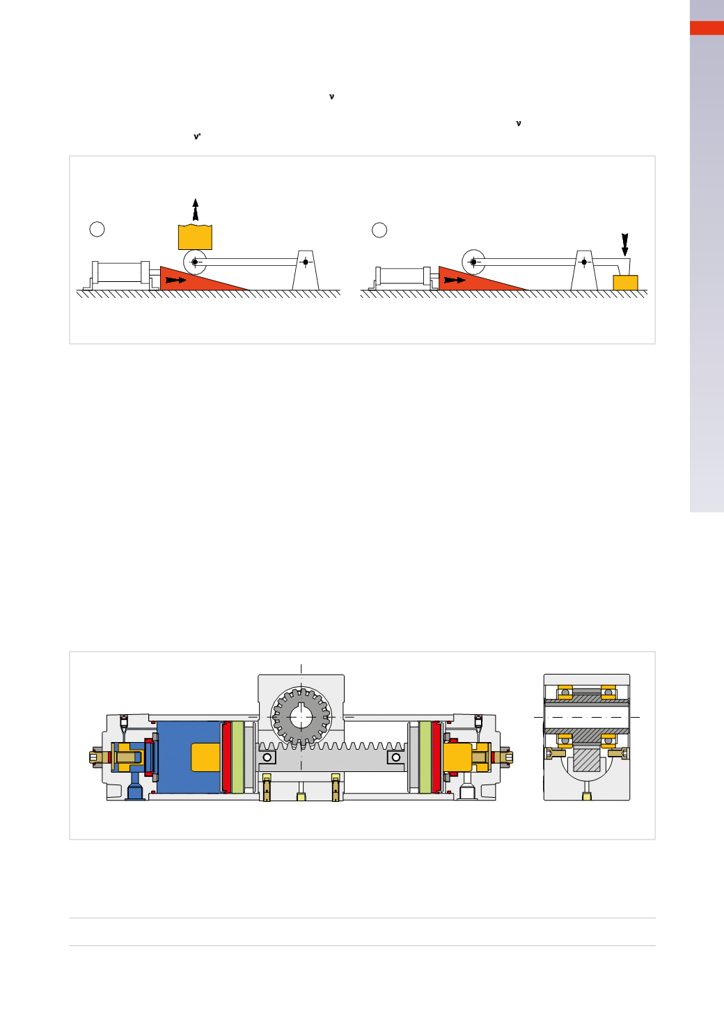
The figures below show how the wedge can be used.
Figure 27
Pos. A
: the sliding friction between load surface
F
ν
and the inclined plane during the lifting phase is transformed
into rolling friction by means of a round body supported by an arm, in this way improving the working conditions.
Pos. B
: this wedge/lever combination improves the ratio between Force
F
s
and Force
F
ν
. It also changes the point
of application of Force
F
ν
.
B
A
Fs
Fv
Fs
Examples of wedge application in equipment
Fv
Fig. 27
Rotary cylinders
Figure 28
The rotating cylinder possesses a number of the features discussed in previous chapters where we illustrated how
to connect a traditional cylinder to a crank or a gear. The pinion/rack group is an integral part of the rotary cylinder
and is connected to the two pistons which each have a magnetic ring in their respective chambers.
The movement of the pistons carries the movement of the rack. The heads are equipped with adjustable end
cushioning and angular adjustment screws; there are also set screws on the central body to offset the slack between
the rack and pinion. The angles of rotation on these cylinders are normally 90° and 180°.
The rotation angle depends on the length of the rack and the number of teeth of the pinion.
The
torque force
M
t
; of the rotary actuator is defined by the distance (in meters) between the axis of the pinion
and the rack, in combination with the thrust Force acting on the rack, this value is decisive in the choice of the
cylinder. This torque Force expressed
Kgm
or
Nm
is obtained by multiplying the thrust Force of the piston acting
on the rack, by the rolling pitch diameter.
Fig. 28
Figure 29
Pos. 1
:
a
indicates the distance between the axis of the pinion and the axis of the rack, and
F
1
indicates the Force
developed by the piston, the torque Force of the cylinder is equal to the product of the two values, namely:
M
t
=
F
1
* a
The Force is expressed as a derivative of the pressure, as is the torque.
3
77
CAMOZZI
>
CYLINDERS