


 76 / 218

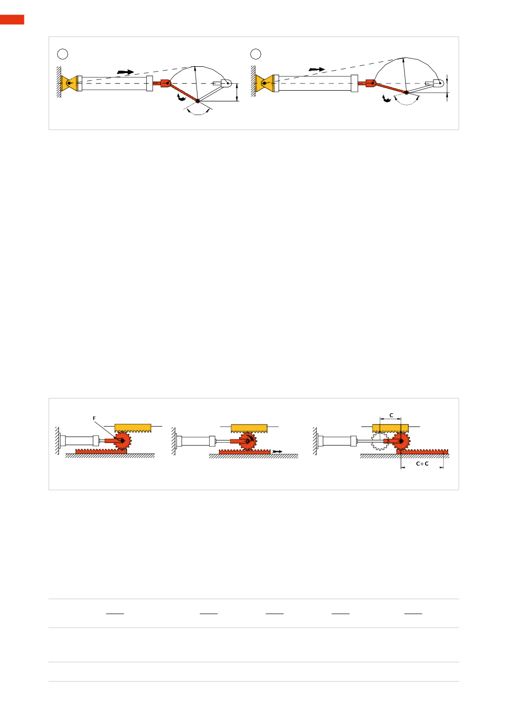
Fs
Fs=Mt : b
2
Mt
120°
b
2
r
Fs
Fs=Mt : b
3
150°
Mt
b
3
r
5
6
Fig. 23
From the previous examples, it appears that for the same length of crank and torque to be overcome, with the
increase of the angle of rotation the stroke length and the cylinder boremust also increase.
With a further increase of the angle, which is equivalent to further reducing the smaller arm, the axis of rotation
of the crank approaches the line of action of the cylinder Force impeding itsmovement, hence the need to use the
crank only for angles of rotation of less than 150°.
At higher angles, the use of rotating cylinders, inwhich the transformation of themovement takes place inside the
cylinder, are needed (as wewill observe in following arguments).
Gearedmechanisms
Geared mechanisms consist of the interaction of at least two gears in such a way that the motion of one gear
results in themovement of the other. The resultingmotion between these components can be:
• from circular to circular;
• from circular to linear;
• from linear to circular.
Since the movement of a cylinder is linear, the motion that we are interested in is from linear to circular.
The set of gears capable of transforming the linear motion into (rotary motion) circular is normally defined “rack
and pinion” (the pinion gear is awheel of small diameter, while the rack is considered awheel of infinite diameter,
so that it forms a straight rod).
Figure 24
In this example, linearmotion is converted into circularmotion to then be transformed again into a linearmotion.
The pinion
F
connected to the rod rotates on the pin, the fixed rack located above, forces the pinion to rotate counter
clockwise transferringmotion to the lower mobile rack.
This rotation is added to the stroke of the cylinder stroke
C
, and the sum of these twomotions, are transmitted to
the lower rack resulting in a stroke twice the stroke
C
of the cylinder.
Fig. 24
Figure 25
Pos. A
: themotion given to the rack through the cylinder is transformed from straight into circular. By varying the
number of teeth of the rack/pinion group, it is possible to have the pinion execute pre-determined rotation angles, or
a different number of revolutions.
Example
: Number of teeth on the rack
Zc
=40
Number of teeth on the pinion
Zp
=20;
Zp
=40;
Zp
=50;
Zp
=80
With the following formulawe calculate the number of rotations of the pinion
N
.rot.pign.
=
Zc
N
.rot.pign.
=
40
=
2
40
=
1
40
=
0,8
40
=
0,5
Zp
20
40
50
80
And the corresponding value in degrees
360 * 2=
720°
360 * 1=
360°
360 * 0,8=
288°
360 * 0,5=
180°
3
74
CAMOZZI
>
CYLINDERS