


 121 / 218

VALVES
A
B
12
12
3
2
2
3
C
D
E
M
F
G
H
1
1
Fig. 54
In the pneumatic symbol, the dimension of the box referring to the pneumatic operation is larger than normal
indicating that this is a valve with a low-pressure activation.
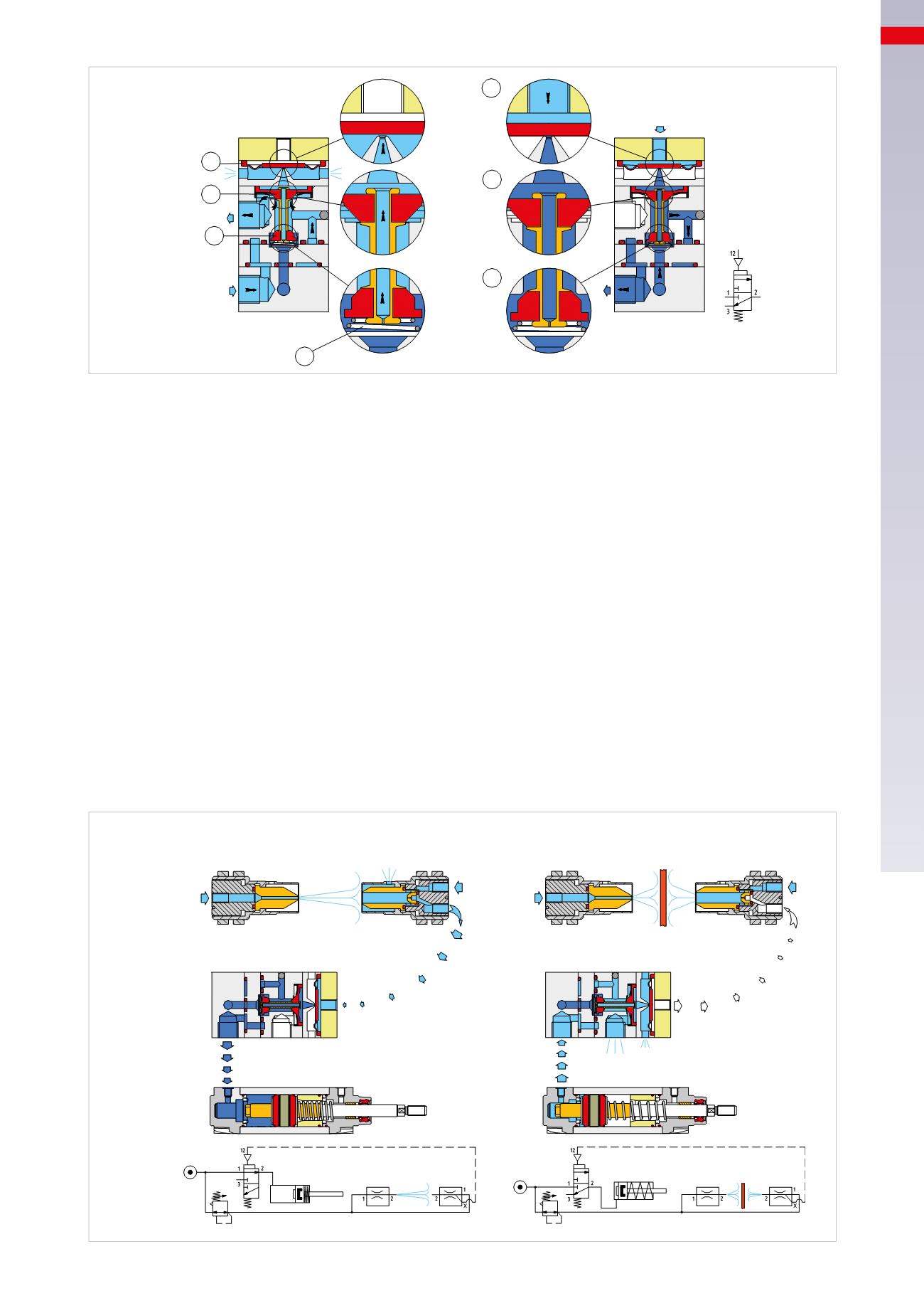
Pneumatic sensors of sender/receiver type (interruption of air stream)
In some applications it may be advantageous to use the sensors that don’t come in contact with the product, and
can operate in the absence of electricity or where the work environment requires the use of “self-cleaning” sensors.
The pneumatic sensors, normally one sender and one receiver, behave as photocells in the sense they interrupt
the pneumatic signal when an object is placed between them. These sensors are especially effective when their
distance is no more than 80
mm
. The shape of the piece placed between the two sensors can vary the sensitivity
of the system.
Figure 55
Pos. A
:
there is no object inserted between the sender and receiver sensors.
The two sensors are powered with low pressure and emit a stream of C/A flowing towards each other. The different
size of the nozzles present in the two sensors causes a variation in the speed of the two air streams generated.
The sender sensor, having a smaller diameter than the orifice, generates a flow with a speed greater than the flow
generated by the receiver sensor. The flow produced by the receiver sensor is unable to enter the atmosphere
because of the faster opposing flow. A flow obstruction of the receiver sensor is created, and not being able to be
released into the atmosphere, a pressure increase is created at outlet 2. This increase in pressure is able to drive
the pressure amplifier connected to outlet 2. The amplifier returns a pneumatic signal.
Pos. B
:
there is an object placed between the sender and receiver sensors.
The flow of C/A coming from the receiver sensor, since it is no longer obstructed by the flow from the sender sensor,
is released into the atmosphere. The receiver sensor no longer directs the flow towards its outlet 2.
A
12
3
2
1
B
12
3
2
1
1
2
2
1
1
1
Sender
sensor
Receiver
sensor
Sender
sensor
Receiver
sensor
Pressure amplifier
Pressure amplifier
Fig. 55
4
119
CAMOZZI
>
VALVES