


 123 / 218

VALVES
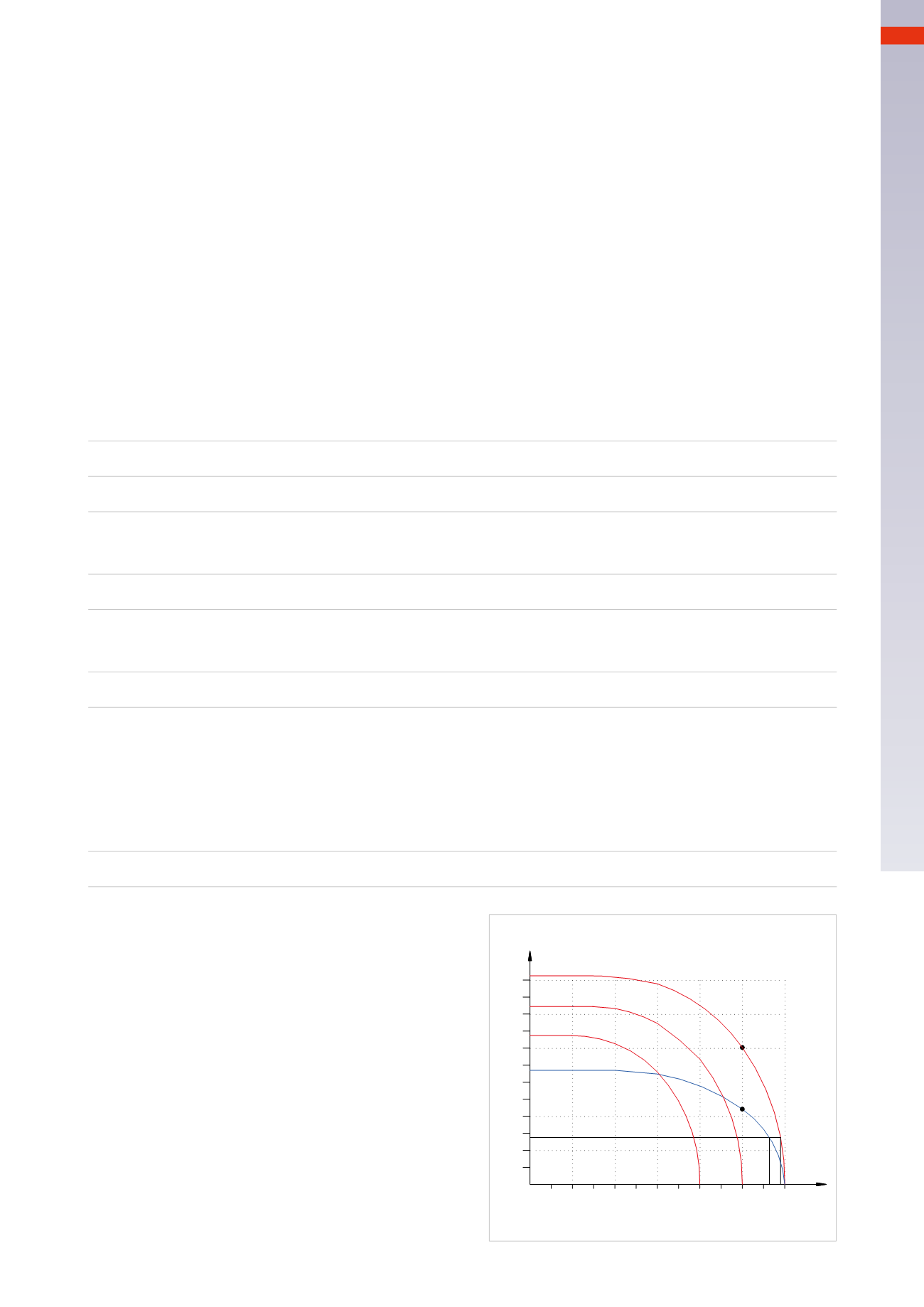
Figure 57
From the graph it is possible to detect the flow
characteristics of two different valves which have M5
and M7 threads respectively.
The required flow rate
Q
r
can be obtained from both
valves, which have a limited pressure drop (
∆
p
)
which varies from 0.1 to 0,4
bar
.
Despite having a cylinder of fixed dimensions as in
this case, it is not necessary to size the valve in relation
to the connection on the heads, but it is possible to
use valves with the best price/size/flow ratio.
Sizing of directional control distribution valves
and connecting tubes
In a pneumatic system a cylinder must move a given load and this must be executed within a designated time.
The first requirement has been addressed in the previous chapters; we now analyze the latter requirement.
The following data must first be determined:
• The volume to fill, for example the cylinder chamber used.
• The time required to complete the stroke.
• The operating pressure.
Valve sizing
Assume we have a cylinder with the following characteristics:
diameter
D
= 50
mm
,
stroke length
c
= 250
mm
stroke,
operating pressure
P
= 6
bar,
timing of the positive stroke
t
= 1,5
sec
.
Calculation of the volume
V
of the cylinder:
V
= Area * Stroke
V
=
r
2
*
π
*
c
V
= (25
[mm])
2
*
π
* 250
[mm]
V
= 490.625
mm
3
V
=
0,49
dm
3
Calculation of the amount of required air
Q
s
to fill the volume
V
at a pressure of 6
bar
in a time
t
= 1,5
sec.
Q
s
=
V
*
P
abs
Q
s
= 0,49
[dm
3
]
*
7
[bar]
Q
s
=
3,43
Nl
This amount should be provided in a time
t
= 1,5
sec
, which expressed in
Q
r
(per minute) becomes:
Q
r
=
(Q
s
/
t
) *
60
Q
r
= (3,43 / 1,5)
*
60
Q
r
=
137
Nl
/
min
The quantity of air required for the valve to move a cylinder:
of diameter
D
= 50
mm
stroke
c
= 250
mm
in a time
t
= 1,5
sec.
is
137
Nl
/
min
Nl/min.
0 0,5 1 1,5 2 2,5 3 3,5 4 4,5 5 5,5 6
100
200
300
400
500
600
Flow curve of the valve
with Qn =
220
and
400
Nl/min
137
Qn
Bar
Qn
Fig. 57
4
121
CAMOZZI
>
VALVES