


 122 / 218

Nominal flow rate
The following factorsmust be consideredwhen selecting components:
• The distribution linemust be dimensioned to fulfil the requirements of the system to be served.
• The larger the flow section, the greater the possible flow rate.
• Any request of air always creates a pressure drop.
• Increasing the request of air, with the same flow section, increases the drop in pressure.
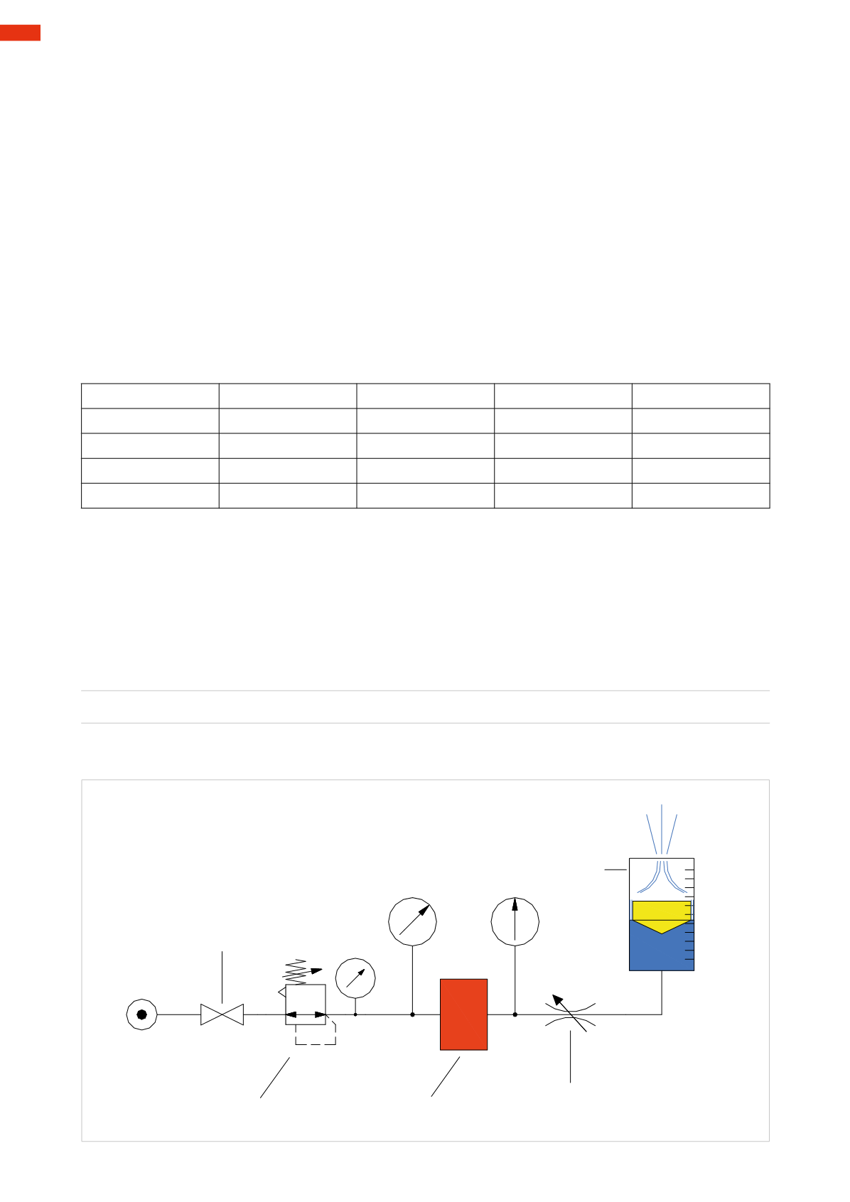
Figure 56
Similar to the distribution line, valves must also be sized correctly in order to be able to provide a quantity of
compressed air sufficient to that required by the equipment in use. The selection should not be based on the size
of the connection, but in reference to the flow rate indicated by the technical data of the product.
In order to have one size as reference, the ISOStandards (International StandardOrganization) prescribes the use
of the term
Nominal Flow
rate as that which every valve effectively supplies perminute in defined test conditions:
• Regulated pressure 6
bar
• Ambient temperature 20
°C
• Pressure drop (
∆
p) 1
bar
Conversion table of themost common units of measurement.
1
kv
Kv
0,06
C
v
0,069
f
0,057
Q
n
67
1
Kv
C
v
1,179
f
1,000
Q
n
1149
kv
16,67
1
C
v
f
0,83
Q
n
962
kv
14,42
Kv
0,85
1
f
Q
n
1159
kv
1,85
Kv
0,97
C
v
1,205
1
Q
n
kv
0,015
Kv
0,0009
C
v
0,001
f
0,0009
kv
= flow of water with
∆
p
= 1
bar
at 20°C [
l/min
]
Kv
= flow of water with
∆
p
= 1
ba
r at temperature ranging from 5°÷40°
[
m³/hour
]
C
v
= Flow of water with
∆
p
= 1
PSI
[
USGallons/min
]
f
= as above but expressed in
Imperial Gallons
Q
n
= nominal flow ratewith inlet pressure 6
bar
and
∆
p
=1
bar
at temperature of 20
°C
[
Nl/min
]
Example
: conversion of a flow rate of 17
kv
into
Qn
:
1
kv
=67
Q
n
[Nl / min]
17
kv
=17 * 67
Q
n
A flow rate of 17
kv
corresponds to a
Q
n
of 1133
Nl/min
.
Pressure regulator
Tested valve
Tapor Ball valve
Flow regulator
Flowmeter
Nl/min.
Fig. 56
4
120
CAMOZZI
>
VALVES