


 143 / 218

CIRCUIT TECHNIQUE
Single or semi-automatic cycle
In circuits, the actuators move at different times according to a defined logical sequence. The various phases,
which comprise the sequence, are dependent upon “confirmation” from the “limit switches”. These are valveswith
mechanical activation devices that are directly operated by the actuators or bymechanical components connected
to them. Because they can be placed anywhere along the stroke, they can be activated at the requiredmoment.
Themachine operator limits his actions to “
Start
” and “
Stop
” controls.
To simplify, we use a single cylinder producing a “
single or semi automatic cycle
” that is to say; for everymanual
operation of the Start command, the cylinder performs only one cycle.
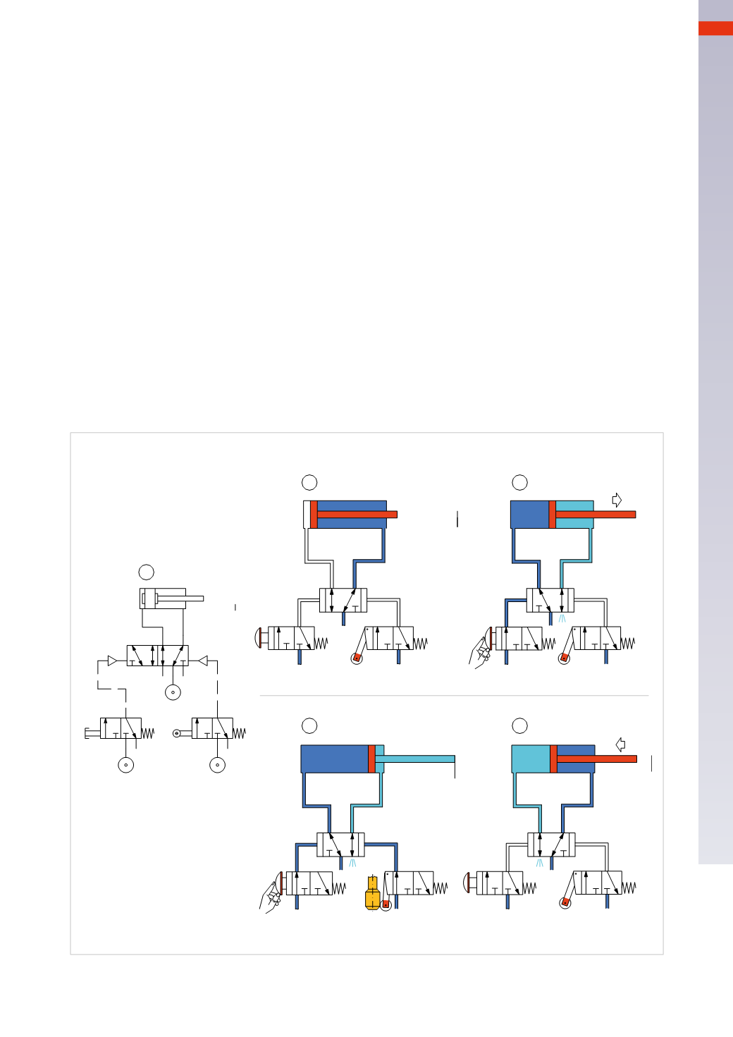
Figure 18
Pos. 1:
the
Start
command is supplied via a manual 3/2-way NC valve with mechanical spring return. The
main
valve
is a pneumatically operated bistable 5/2-way valve. The repositioning command is supplied by amechanically
operated 3/2-wayNC valvewith spring return.
Pos. 2:
the bistable 5/2-way valve does not have a definite rest position and either outlet (2 or 4) may be active.
In this specific case, as neither the start button nor the limit switch are actuated, themain valve feeds the cylinder
therefore the piston rod/piston is in the negative end position.
Pos. 3:
as theStart button is activated, themain valve receives the pilot signal 14, and the passage between inlet 1
and outlet 4 is opened, outlet 2 exhausts through exhaust port 3. The compressed air feeds the positive chamber of
the cylinder,moving the piston rod/piston until it reaches the positive end position.
Pos. 4:
when arriving at the positive end position, indicated by the vertical line, the piston rod actuates the limit
switch through the mechanical actuation device, whereby the passage between inlet 1 and outlet 2 is opened,
delivering the pilot signal 12 to the main valve in order for the signal to proceed, there can be no signal coming
from the Start button.
Pos. 5:
Upon releasing theStart button, the piston rod/piston detaches from the end position, the limit switch closes
the passage between inlet 1 and outlet 2 and releases the pilot signal to themain valve through connection 3.
1
2
3
4
5
1
3
5
2
4
14
1
2
3
12
1
2
3
12
12
Fig. 18
The repetition of the cycle is possible if the start valve is re- activated.
5
141
CAMOZZI
>
CIRCUIT TECHNIQUE