


 144 / 218

1
3
5
2
4
14
12
1
2
3
12
1
2
3
12
10
1 3
12
IC
IC
1
2
3
4
5
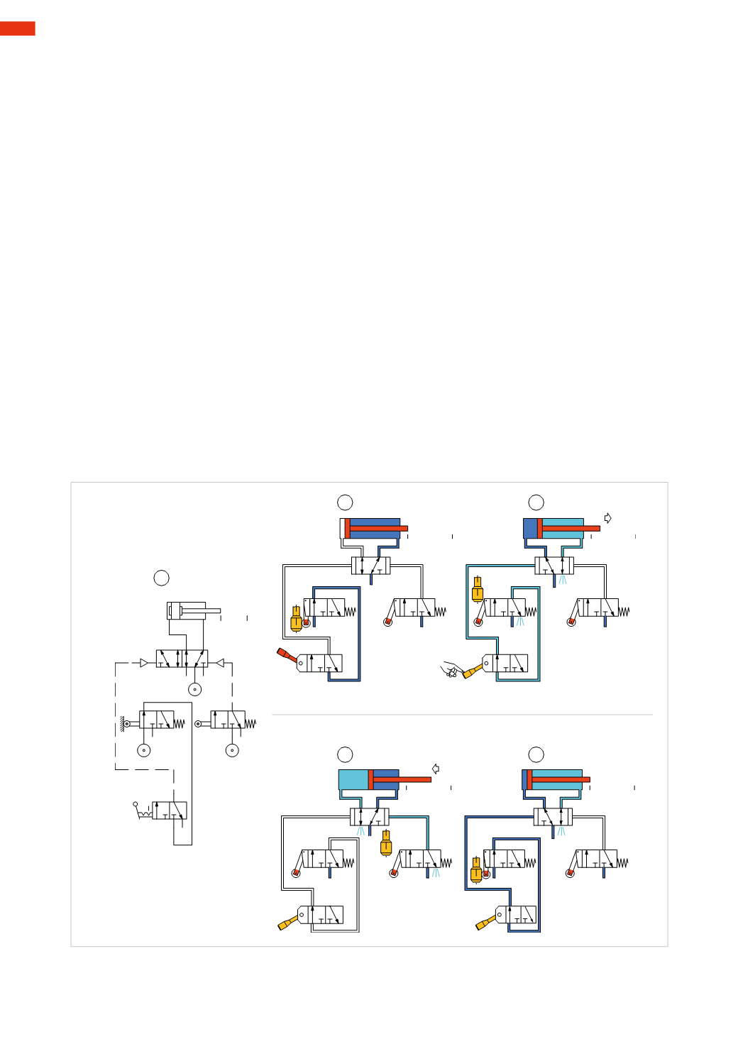
Fig. 19
Continuous or automatic cycle
In the previous circuit, it was possible to achieve the automatic return of the cylinder using a mechanical valve
(limit switch) at the end of the positive stroke position. For the cycle to continue automatically, anothermechanical
valve (limit switch)wouldneed to be inserted, togetherwithanadditional “Start” function, as theStart/EndCycle
command is always given by the operator.
In this example (as in the previous) we will use only one cylinder completing a
continuous or automatic cycle
.
This implies that the cycle is repeated automatically, providing the operator doesn’t switch themanually operated
valve to its “End Cycle” position.
Figure 19
Pos. 1:
in contrast to the previous single or semi-automatic cycle, the “start” button is replaced by a manually
operated bistable 3/2-way valve (
I.C-start cycle
) representing the functions “Start/End Cycle”, whose air supply is
determinedby the state of the limit switchat thenegative endposition. The
main
valve is apneumatically operated
bistable 5/2-way valve.
Pos. 2:
the compressed air is present at the inlet of all of the valves; it passes through the 5/2-way valve, which
feeds the negative chamber of the cylinder. The negative limit switch (located at the negative end position), being
activated, feeds the
I.C.
valve, which in this state does not permit the start of the cycle.
Pos. 3:
by moving the lever of the
I.C.
valve there is passage of compressed air towards the main valve which
is commanded now receiving the pilot signal 14, allowing the movement of the piston rod/piston towards
the positive end position. The piston rod/piston via its movement, releases the negative limit switch closing the
passage of compressed air, permitting the exhaust of the pilot signal. The operation of the
I.C.
valve is not needed
as it is bistable, and therefore its position ismaintained.
Pos. 4:
the piston rod/piston reaches the positive limit switch which is thereby activated, and through its outlet
2, feeds the pilot signal 12 to the main valve which changes over and inverts the direction of air in the cylinder
chambers. The piston rod/piston begins returning towards the negative end position. The positive limit switch is
released through themovement of the piston rod/piston.
Pos. 5:
the piston rod/piston reaches the negative end position, activating the negative limit switch. The outlet
2 of this switch feeds the
I.C.
valve. The cycle will continue to repeat automatically, assuming the operator does
not intervene.
If the lever of the
I.C.
valve is repositioned, regardless of its position, the piston rod/pistonwill continue itsmovement
until the completion of the cycle, and then stops.
5
142
CAMOZZI
>
CIRCUIT TECHNIQUE