


 170 / 218

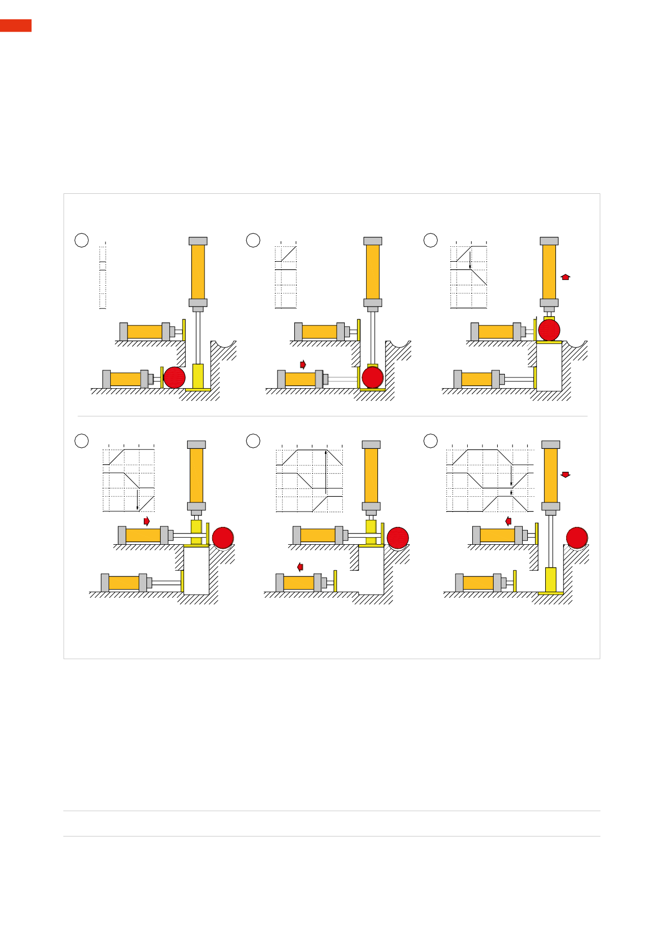
Movement of multiple cylinders
In this example, the cycle includes three cylinders whosemovements are defined by the following conditions:
Figure 66
Pos. 1
:
verification the bar is at the input and the exit chute is free
Pos. 2
:
introduction of the bar in the lift
A+
Phase 1
Pos. 3
:
bar is lifted
B –
Phase 2
Pos. 4
:
ejection of the bar towards the exit chute
C+ Phase 3
Pos. 5
:
return of the pusher cylinder
A –
Phase 4
Pos. 6
:
return of the ejector and lifting cylinders
B+C –
Phase 5
B
-
-
+
A
+
-
+
C
1
B
-
-
+
A
+
1
a1
-
+
C
B
-
-
+
A
+
1 2
a1
-
+
C
B
-
-
+
A
+
1 2 3
b0
-
+
C
B
-
-
+
A
+
1 2
c1
3 4
-
+
C
B
-
-
+
A
+
1 2
a0
3 4 5
-
+
C
A
C
B
A
C
B
A
C
B
A
C
B
A
C
B
A
C
B
1
2
3
4
5
6
Fig. 66
Unlike in thepreviousexample,mechanicallyoperated limit switchesareused todetect thepositionof thecylinders.
The start command is provided through aStart Cycle
I.C.
valve. In addition to verifying the presence of the bar, the
piston rod/piston of both cylinders
B
and
C
must have completed their respective strokes during the starting phase.
It is necessary to consider whether the signal is continuous or an impulse signal when selecting the type of main
valve. Unlike amonostable valve, the choice of a bistable valve prevents the continuation of the pilot signal.
The cylinders and their respective limit switches are represented in their initial state, and the connection lines from
themain valves to the cylinders are drawn. The connections and lines regarding the limit switches shall be drawn
so as to avoid intersecting connecting lines asmuch as possible.
Figure 67
Introduction of the bar in the lift
I.C. * b1 * c0=
A+ Phase 1
The action on the
I.C.
valve generates a signal that crosses the limit switches
b1
and
c0
, which in this phase are
operational and therefore open. This signal, connected to pilot port 14 of the main valve of cylinder
A
, initiates
the positive stroke and the completion of phase
A+
. In the absence of an air passage at the
I.C.
,
b1
or
c0
, the
cycle cannot start.
5
168
CAMOZZI
>
CIRCUIT TECHNIQUE