


 171 / 218

CIRCUIT TECHNIQUE
B
-
-
+
A
+
-
+
C
P.B.
Presence
of theBar
S.V.
Vacuum
Chute
I.C.
1
b1
c0
I.C. * b1 * S.V. * c0 * P.B. =A+
c0
b1
Cil. "C"
Cil. "B"
Cil. "A"
b0 b1
a0 a1
c0 c1
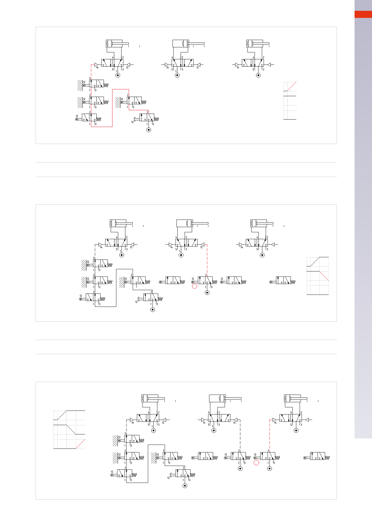
Fig. 67
Figure 68
Lifting of the bar
a1
=
B –
Phase 2
Once limit switch
a1
is reached, a signal is generated; this signal, if sent to pilot port 12 of the main valve of
cylinder
B
, dictates the return of the piston rod/piston and the completion of Phase
B –
.
Cil. "A"
Cil. "B"
Cil. "C"
c0
b1
a0 a1
b0 b1
c0 c1
B
-
-
+
A
+
-
+
C
a1=B-
a1
I.C.
a1
1 2
P.B.
Presence
of theBar
S.V.
Vacuum
Chute
Fig. 68
Figure 69
Ejection of the bar towards the exit chute
b0
=
C+ Phase 3
Once limit switch
b0
is reached, a signal is generated; this signal, if sent to pilot port 14 of the main valve of
cylinder
C
, dictates the positive stroke of the piston rod/piston and the completion of Phase
C+
.
B
-
-
+
A
+
-
+
C
b0
c0
P.B.
Presence
of theBar
S.V.
Vacuum
Chute
b1
a1
b0
I.C.
b0=C+
1 2 3
Cil. "C"
Cil. "B"
Cil. "A"
b0 b1
a0 a1
c0 c1
Fig. 69
5
169
CAMOZZI
>
CIRCUIT TECHNIQUE