


 172 / 218

B
-
-
+
A
+
1 2
a0
3 4
-
+
5
a1
b0
c1
b0
b1
c0
C
I.C. * b1 * c0 = A+
a1 = B-
b0 = C+
c1 = A-
a0 = B+C-
a0=B+C-
Cil. "A"
Cil. "B"
Cil. "C"
c0
P.B.
Presence
of theBar
S.V.
Vacuum
Chute
b1
c1
a1
b0
a0
a0 a1
b0 b1
c0 c1
I.C.
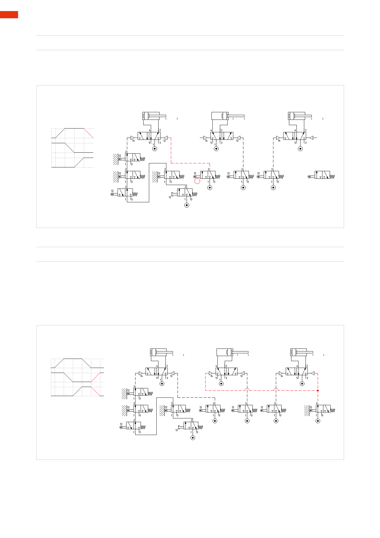
Fig. 71
Figure 70
Return of the feeder cylinder
c1
=
A –
Phase 4
Once limit switch
c1
is reached, a signal is generated; this signal, if sent to pilot port 12 of the main valve of
cylinder
A
, dictates the return of the piston rod/piston and the completion of Phase
A –
. Pilot signal 12 can switch
the valve of cylinder
A
, as the positions of the limit switches
b1
and
c0
are altered and pilot signal 14 is absent.
c0
b1
c1
a1
b0
I.C.
B
-
-
+
A
+
-
+
C
c1=A-
c1
1 2 3 4
P.B.
Presence
of theBar
S.V.
Vacuum
Chute
Cil. "C"
Cil. "B"
Cil. "A"
b0 b1
a0 a1
c0 c1
Fig. 70
Figure 71
Return of the ejecting- and lifting cylinder
a0
=
B+C – Phase 5
With the operation of limit switch
a0
, a signal is generated; this signal, if sent to pilot port 14 of themain valves
of cylinders
B
and
C
(which, by changing over), allow the return of the piston rod/pistons of the two cylinders to
the cycle start positions, i.e.
B+
and
C –
. The limit switch
a0
is represented as actuated, as in the beginning of a
cycle. The changing over of themain valves is assured by the duration of the signal present throughout the entire
Phase 5.
The position of the actuators is the same as in the initial condition, onlywith the consent of the
I.C.
valve and the
limit switches
b1
and
c0
activated the cycle can start.
Figure 72
This circuit uses
bistable
main valves as themain valve of the cylinder
A
cannot bemonostable since pilot signal
14 is influenced by the presence of the limit switches
b1
,
c0
and the
I.C.
command. Also the main valve of the
cylinder
B
cannot bemonostable in fact the limit switch
a1
whichgenerates thenegative stroke remains operational
until the end of Phase3, and not piloting the valve anymore, it wouldmore the cylinder, however its positionmust
bemaintained also during Phase 4. Only themain valve of cylinder
C
may bemonostable.
5
170
CAMOZZI
>
CIRCUIT TECHNIQUE