


 176 / 218

a1
b0
IC
A
B
a1
a0
b0 b1
a0
b1
1
2
Fig. 76
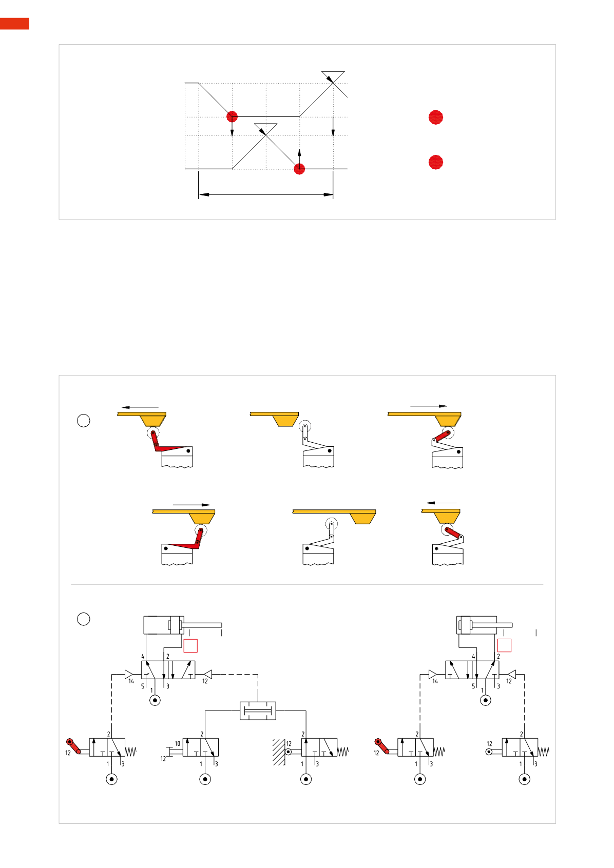
Figure 76
Nowwe replace the actuator limit switches
a0
and
b0
with a undirectional roller lever.
Pos. 1
: the switch can only be actuated from one direction. Due to effect of the “knee” joint, the drive from the
opposite side causes the lever to flex and the valve does not generate any signal.
It is important that this valve remains non-actuated at the end position of the cylinder and therefore must be
installed so that the control cam releases the actuating device in this position. The duration of the output signal
will depend on the length of the cam and the speed of the cylinder. A cam that is too short or a cylinder whose
speed is too high could generate an output signal whose very short duration could be insufficient to command the
changeover of themain valve.
Pos. 2
: pneumatic circuit using the limit switch with a unidirectional roller lever. In this case the limit switches
a0
and
b0
are no longer blocking signals - the cycle is not interrupted.
b0
B
A - = IC * a1
B+= a0
B - = b1
A+= b0
-
cycle
-
+
A
+
a0
1
2
a1
b1
3
4
Fig. 75
5
174
CAMOZZI
>
CIRCUIT TECHNIQUE