


 174 / 218

_C
+
+
_C
B_
+
+
_A
+
_C
a0
B_
+
+
_A
c0
1
B
+
_
+
_A
A+
6 5 4
2 3
C-
C+ B+ A-
B-
+
A
B_
+
_C
+
_
a1
+
A
B_
+
C_
+
_
b1
+
C_
B_
+
A
+
_
b0
A
+
_B
C
+
_
+
_
c1
cycle
A+= I.C. * b0
B+= a1
C+= b1
A- = c1
C- = a0
B- = c0
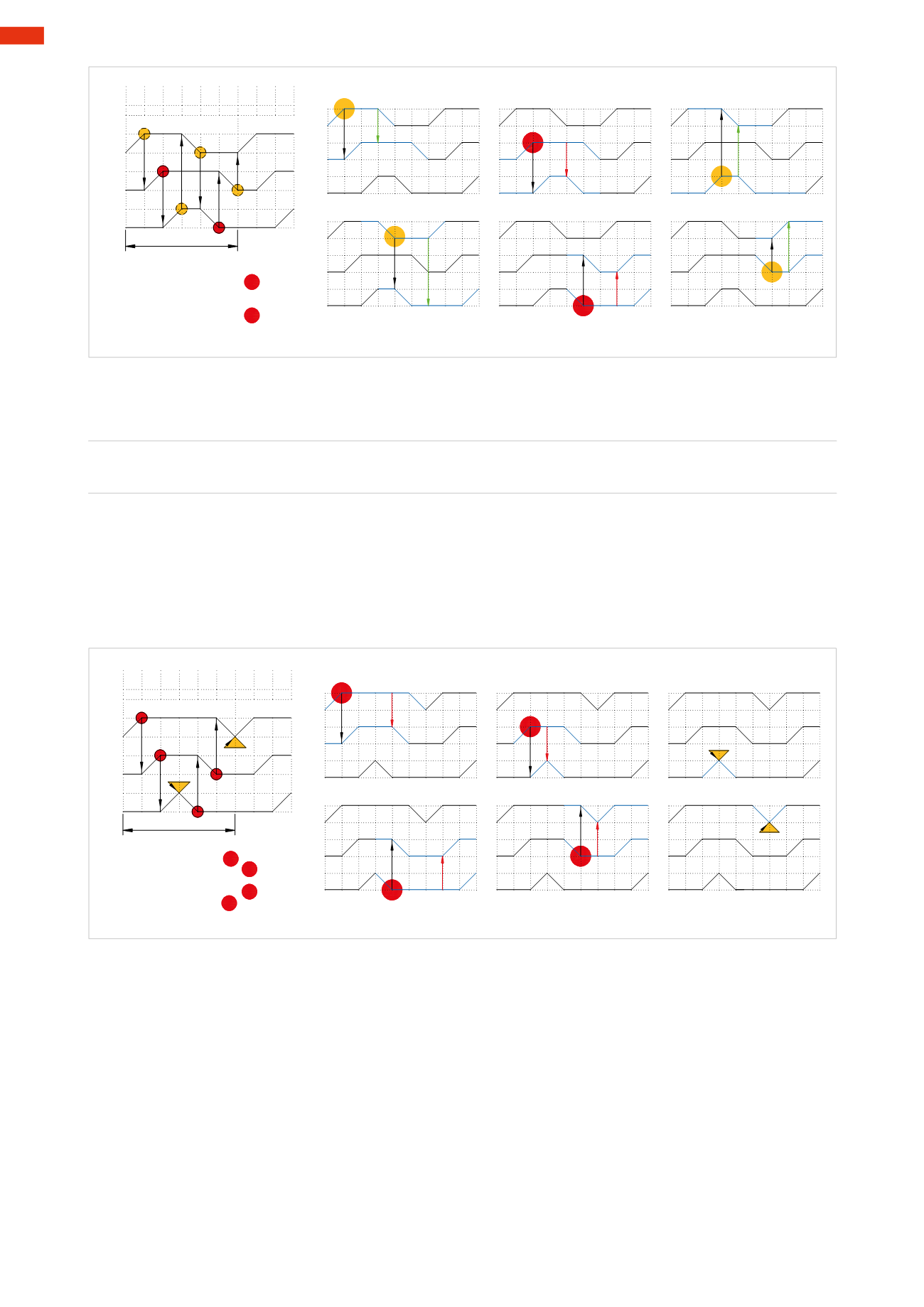
Fig. 73
Figure 74
Similarly, for the following sequence:
A+ / B+ / C+ / C – / B – / A –
1
2
3
4
5
6
Signal
a1
:
blocking
as it is active during Phase 5, when cylinder
B
must return
Signal
b1
:
blocking
as it is active during Phase 4when cylinder
C
must return
Signal
c1
:
immediate
as it only serves cylinder
C
on its return
Signal
a0
:
blocking
as it is active during Phase 2, when cylinder
B
must execute its positive stroke
Signal
c0
:
blocking
as it is active during Phase 1, when cylinder
A
must execute its positive stroke
Signal
b0
:
immediate
as it is the last received signal, and it is generated at the end of the cycle.
It confirms the start of the cycle.
a1
+
C_
_
+
B
A_
+
A+
1
c0
A+= I.C. * a0
B+= a1
C+= b1
C- = c1
B- = c0
A- =b0
cycle
A
_B
+
_C
+
_
+
+
_C
B_
+
B-
3
C+ B+
2
C-
4
A-
5 6
A_
+
b1
A
B_
+
C_
+
_
+
+
_C
_B
+
b0
A_
+
A
_B
C
+
_
+
_
+
C
+
_
B_
+
c1
a0
A_
+
Fig. 74
Relationshipsbetween signalsandmovementsaredepictedon flowdiagrams,where the signal becomesa
blocking
signal it will be highlighted in red.
5
172
CAMOZZI
>
CIRCUIT TECHNIQUE