


 173 / 218

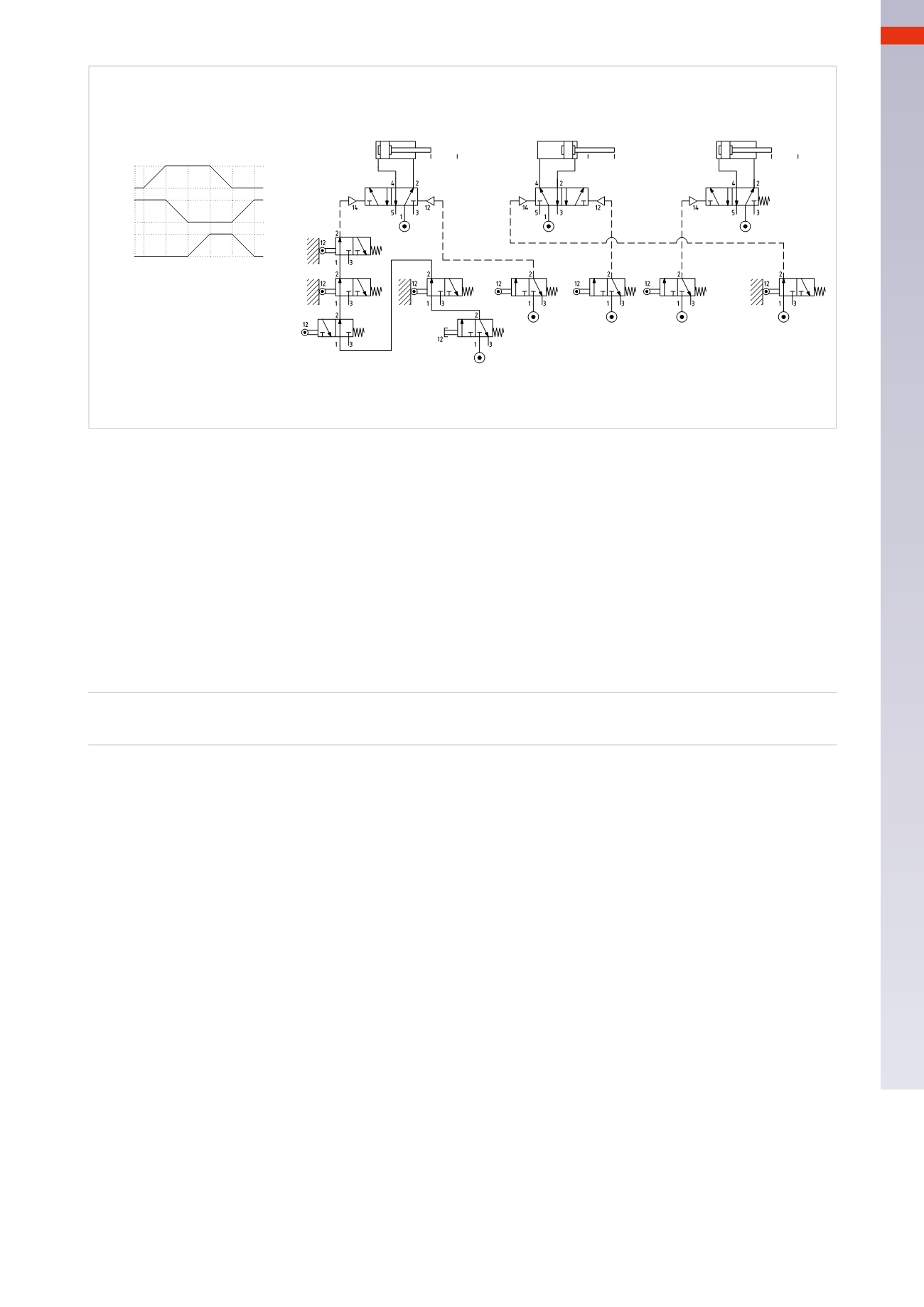
CIRCUIT TECHNIQUE
B
-
-
+
A
+
a0
-
+
b0
c1
b0
b1
c0
C
Cil. "A"
Cil. "B"
Cil. "C"
c0
b1
c1
a1
b0
a0
a0 a1
b0 b1
c0 c1
I.C.
P.B.
Presence
of theBar
S.V.
Vacuum
Chute
1 2 3 4 5
a1
I.C. * b1 * c0 = A+
a1 = B-
b0 = C+
c1 = A-
a0 = B+C-
Fig. 72
Identification of blocking signals
Upon examining the previous sequences, we observed that the signals generated from the limit switches did not
always guarantee the continuity of the cycle. The three types of signals are:
immediate
,
prolonged
and
blocking
.
The blocking signals are those signals which impede the continuation of the cycle.
Figure 73
We examine one of the previous sequences:
A+ / B+ / C+ / A – / C – / B –
1
2
3
4
5
6
When constructing the sequence; the blocking signals and the destination of their respective output signalsmust
be identified. To do this we represent them individually.
Signal
a1
: what is the origin? The limit switch - activatedwhen position
A+
has been reached.
What is its function? To generate the positive stroke of cylinder
B
through themain valve.
The signal disappears during phase 4, it does not obstruct the return of the cylinder
B
during Phase 6.
The signal is
prolonged
as it is present during Phases 2 and 3.
Signal
b1
: what is the origin? The limit switch, activatedwhen position
B+
has been reached.
What is its function? To generate the positive stroke of cylinder
C
through themain valve.
The signal is still present during phase 5when cylinder
C
should be returning.
This is a
blocking
signal (as it obstructs the return of cylinder
C
).
Signal
c1
: what is the origin? The limit switch, activatedwhen position
C+
has been reached.
What is its function? To generate the negative stroke of cylinder
A
via themain valve.
The signal disappears during phase 5; it does not obstruct the return of cylinder
A
during Phase 4.
The signal is
prolonged
as it is present during Phase 4.
Signal
a0
: what is the origin? The limit switch, activatedwhen position
A –
has been reached.
What is its function? To generate the negative stroke of cylinder
C
via themain valve.
The signal disappears during phase 1; it does not obstruct the positive stroke of cylinder
C
.
The signal is
prolonged
as it is present during Phases 5 and 6.
Signal
c0
: what is the origin? The limit switch, activatedwhen position
C –
has been reached
What is its function? To generate the negative stroke of cylinder
B
via themain valve.
The signal is present during both stroke lengths of cylinder
B
.
This is a
blocking
signal.
Signal
b0
: what is the origin? It is the last received signal and it is generated at the end of each cyclewhen the
cylinder
B
terminates the negative stroke.
What is its function? To generate the positive stroke of the cylinder
A
through themain valve.
The signal disappears during Phase 2; it does not obstruct the return of cylinder
A
.
The signal is
prolonged
.
5
171
CAMOZZI
>
CIRCUIT TECHNIQUE