


 177 / 218

CIRCUIT TECHNIQUE
We analyze the individual phases of the sequence, determining the possibility of, andmethods for, eliminating the
blocking signals.
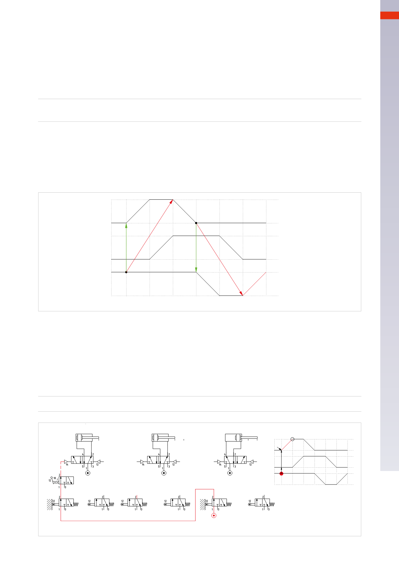
Figure 78
Phase 1
:
A+
The signal from limit switch
a0
which enables the start of cylinder
C
, is a blocking signal, as it remains active
during both strokes of the cylinder. This can be avoided by feeding it through limit switch
b0
, which remains until
the end of Phase 1. The limit switch
a0
re-activates at the end of phase 5when the piston rod/piston of cylinder
B
actuates limit switch
b0
.
A+
=
b0 * c1 * I.C.
A+=b0 * c1 * I.C.
B
C
+
-
5
A
I.C.
1
2
a1
4
6 1
3
+
-
+
-
b0
c1
c1
b0
a0 a1
b0 b1
c0 c1
A
B
C
I.C.
Fig. 78
In the previous paragraphwe eliminated the blocking signals by changing the type of limit switch.
We now proceedwith the alternative solutions, such as
controlling the air supply
.
This control can be achieved by the following two techniques:
• the technique of the connections
• the technique of thememories.
The Technique of the Connections
Consider the sequence
A+ / B+ / A – / C – / B – / C+
1
2
3
4
5
6
Figure 77
While preparing the flow diagram, we observe the
blocking
signals generated by:
• limit switch
c1
,which indicates the positive position of the piston rod/piston of the cylinder
C
and combinedwith
the other signals, enables the beginning of the cycle with the start of movement
A +
; it remains active also
during Phase 3 and blocksmovement
A –
.
• limit switch
a0
, indicates thenegativepositionof thepiston rod/pistonof cylinder
A
andenables the
C–
movement.
It remains active also during phase 6 and blocksmovement
C+
.
B
C
+
-
5
A
1
2
4
6
1
3
+
-
+
-
a0
c1
Fig. 77
5
175
CAMOZZI
>
CIRCUIT TECHNIQUE