


 191 / 218

CIRCUIT TECHNIQUE
I.C.
U6
a0
U1
U1
a0 a1
a0 *U6=U1 * I.C. =
A+
I.C.
U6
a0
a0 a1
b0 b1
a1
U2
a1 *U1=U2
=
B+
U1
U2
Cil. "A"
Cil. "B"
U1
U1
U2
U1
U2
Cil. "A"
MS1
MS2
MS1
MS2
1
2
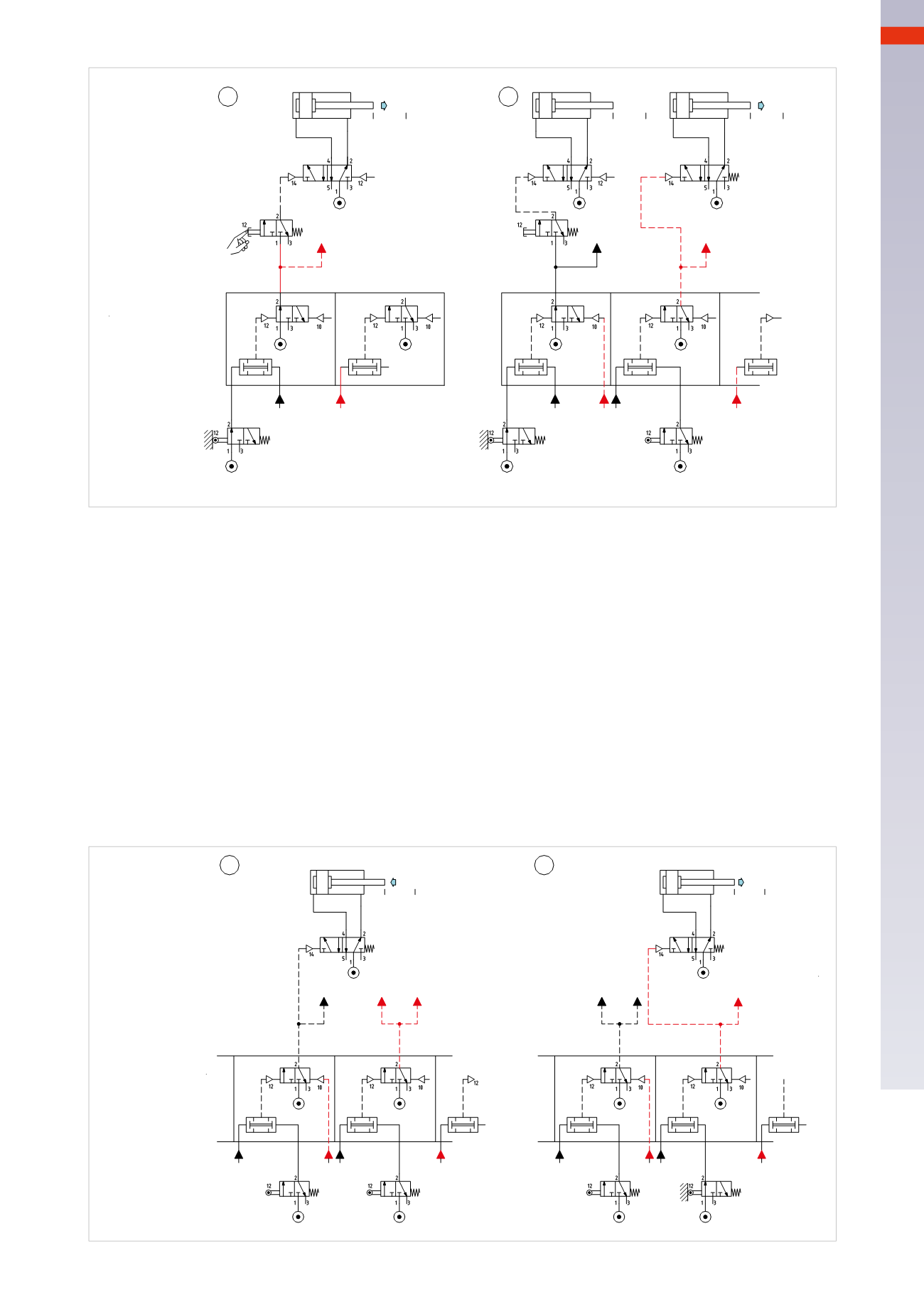
Fig. 99
Figure 100
Pos. 3
: once thepiston rod/pistonof cylinder
B
has completed its positive stroke, it actuates limit switch
b1
,which
emits anoutput signal. This signal, and the confirmationof thepresenceof
LineU2
are connected to the two inlets
of the
AND
element of sequencer
MS3
. The output of the
AND
operates thememory valve which by opening the
passage, generates
LineU3
.
With the activation of the
LineU3
we have:
• the reset of the memory valve of sequencer
MS2
and consequently the interruption of
Line U2
, the changing
over of themain valve of cylinder
B
(monostable) and the return of the piston rod/piston of cylinder
B
• preparation of the
AND
function of sequencer
MS4
.
Pos. 4
: once the piston rod/piston of cylinder
B
has completed its negative stroke, it actuates limit switch
b1
,
which emits an output signal. This signal, together with the confirmation of the presence of line
U3
, is connected
to the two inlets of the
AND
element of sequencer
MS4
. The output of the
AND
operates thememory valvewhich
generates
LineU4
by opening the passage.
With the activation of the
LineU4
we have:
• the operation of themain valve of cylinder
C
in order to obtain the positive stroke
C+
• the reset of thememory valve of sequencer
MS3
and the consequent interruption of
U3
• preparation of the
AND
function of sequencer
MS5
.
b1 * U2=
U3
=B
-
b0 * U3=
U4
=C+
U1
b0 b1
Cil. "B"
a1
U2
U3
U3
b1
U2
c0 c1
Cil. "C"
b1
U3
U4
U4
b0
U4
U3
MS2
MS3
MS4
U2
U3
U3
U3
U4
MS3
MS4
MS5
3
4
Fig. 100
5
189
CAMOZZI
>
CIRCUIT TECHNIQUE