


 193 / 218

CIRCUIT TECHNIQUE
I.C.
U6
a0
U2
U1
a0 a1
Cil. "A"
b0 b1
Cil. "B"
c0
c1
Cil. "C"
U1
a1
U3
U2
b1
U2
U4
U3
b0
U5
U4
c1
U6
U5
c0
U3
U4
U5
U6
U1
U3
U5
U2
U1
U4
U6
MS1
MS2
MS3
MS4
MS5
MS6
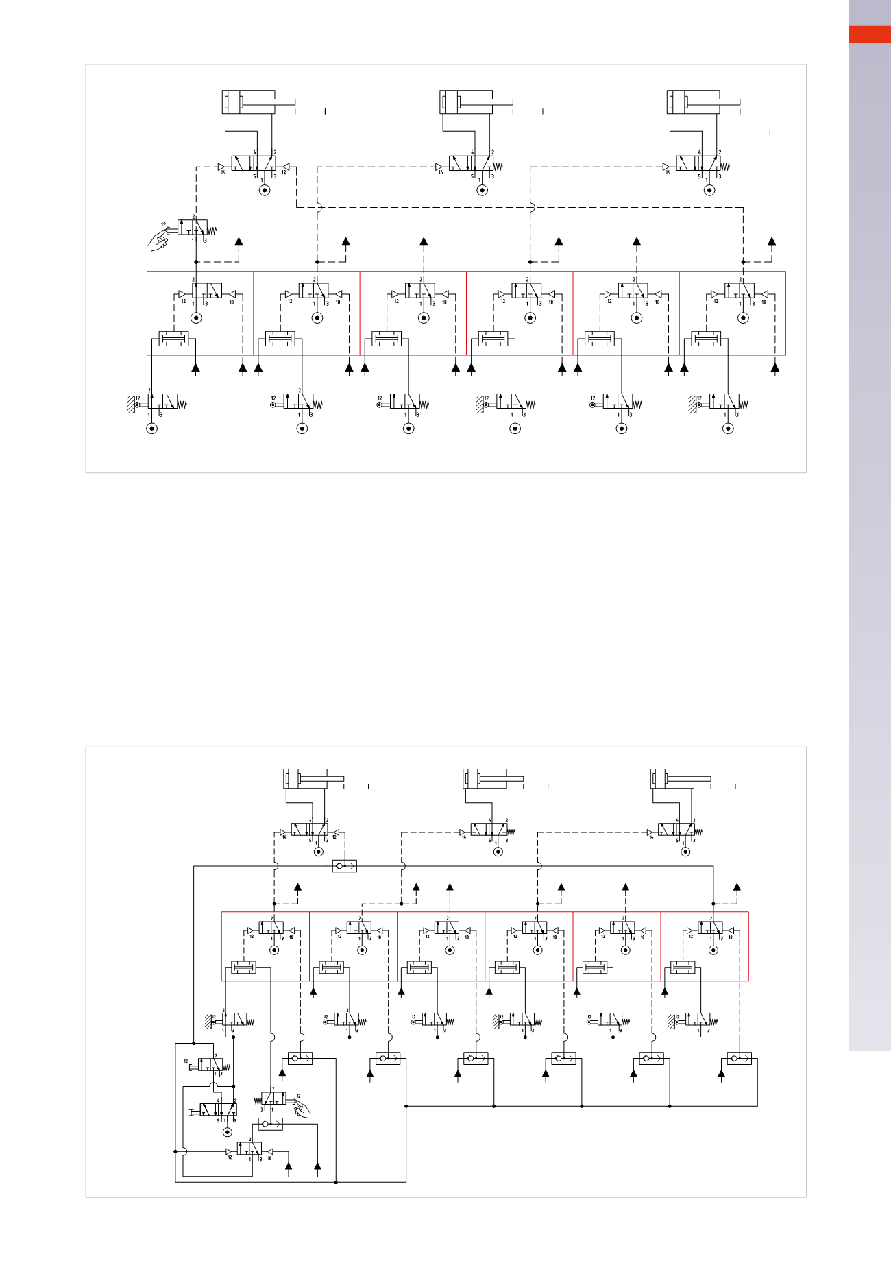
Fig. 102
Figure 103
With this example the emergency stop and cycle reset commands are introduced.
Emergency
: a bistable 5/2-way valve has been used, in the shown position it feeds all the limit switches; when
actuated it doesn’t allow the sequencer to continue the cycle, as it interrupts the compressed air supply,
stopping
the cycle in its current Phase.
Resetting the
EM
command, the sequencer
resumes from the Phase inwhich it had stopped
.
Reset
: this command is active only during the
EM
phase. If actuated, the memory valves of all the sequencers
(
MS
) will reset, putting them in the closed position, the bistable valvewhich controls cylinder
A
repositions itself.
Another function is to prepare the 3/2-way memory valve to feed the
I.C.
command via the
OR
function and the
U6
command in the
open
position
.
As indicated in the previous chapters, the
EM
and
Reset
functions must be properly analyzed in order to prevent
damage to equipment. The example described above is for educational purposes only.
a0
U1
a0 a1
Cil. "A"
b0 b1
Cil. "B"
c0 c1
Cil. "C"
a1
U2
b1
U3
b0
U4
c1
U5
c0
U3
U5
Reset
U2
U4
U6
MS1
MS2
MS3
MS4
MS5
MS6
U3
U4
U5
U6
U1
I.C.
U2
EM.
U6
U1
U1
Fig. 103
5
191
CAMOZZI
>
CIRCUIT TECHNIQUE