


 189 / 218

CIRCUIT TECHNIQUE
The sequencer
The preliminary analysis required will depend on the method adopted for the realization of the circuit, as regards
to the feeding of the air supply to the limit switches that generate blocking signals.
In certain cases, the circuit can be simplified by repeatedly using at least two pneumatic functions, a 3/2-way
memory valve and a logic AND function. These elements can be connected and integrated in a single device –
sequencer
.
With the sequencer device, the blocking signals or their duration are no longer determinant.
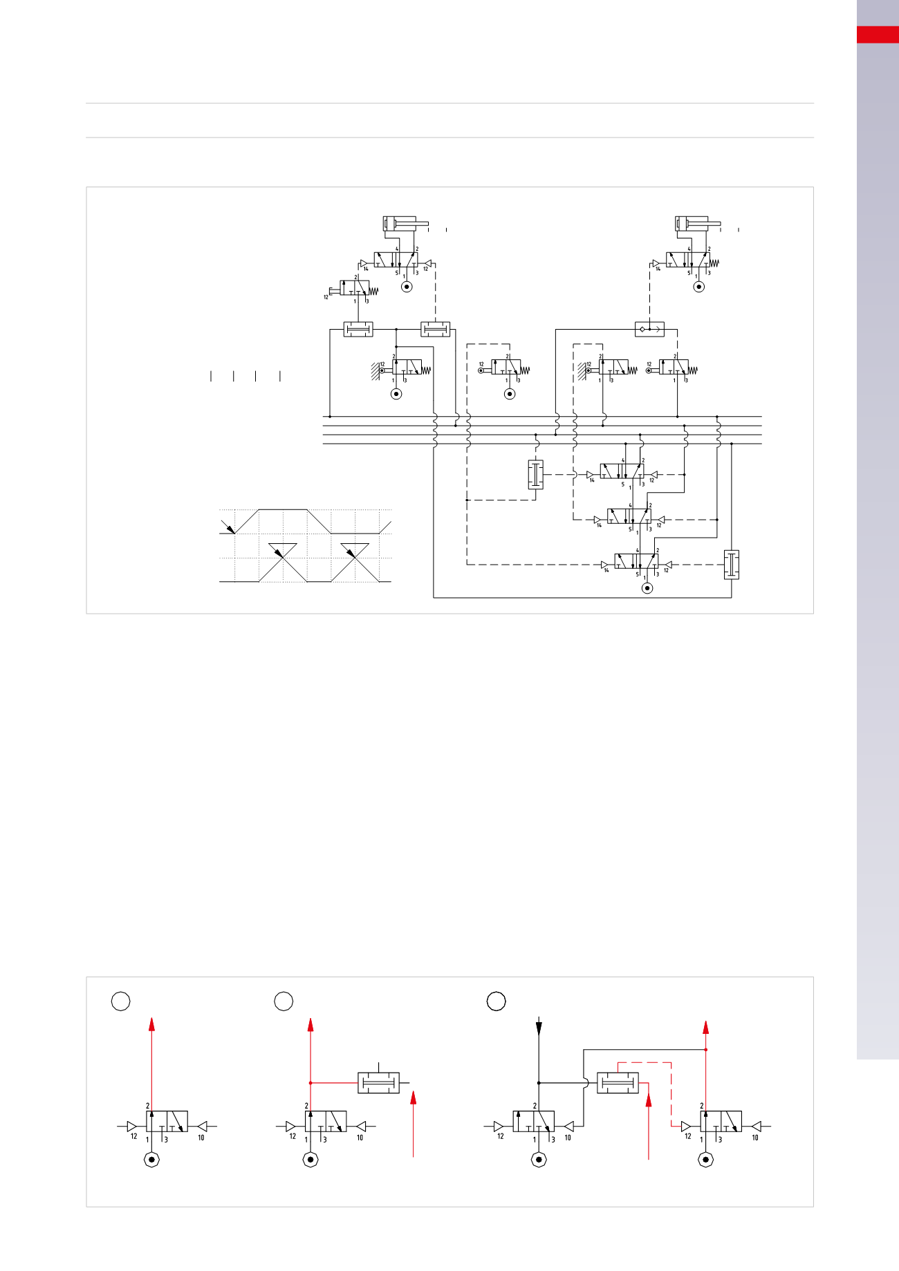
Figure 97
Pos. 1
: a
3/2-way
memory valve is drawn in the
open
position and fed by the main compressed air network,
its output is defined as
U1
. This output allows the advancement of the cycle or to feed the Start button with
compressed air.
Pos. 2
: the output
U1
is connected to an
AND
function in parallel. The output of this function is only activated in
the presence of signal
S1
from the first limit switch actuated after the start of the cycle.
Pos. 3
: the signal
S1
is now present, the output of the
AND
function is active and operates the memory valve of
the successive sequencer, which generates output
U2
by opening. This output, in addition to being used as a pilot
signal for valves in the circuit, closes the
3/2-way
memory valve which generated
U1
. Closing the memory valve,
output
U1
is exhausted and consequently also the pilot signal
12
of the memory valve that generated output
U2
.
1
2
3
U1
U1
U1
U2
S1
S1
Fig. 97
Cil. "A"
Cil. "B"
a0 a1
b0 b1
b0
a1
a0
b1
U1
U2
U3
U4
U1
U2
U3
U4
I.C.
S1
S2
S3
S4
+
+
-
B
-
A
I.C.
1 2 3
5 4
6 1
a1
b1
b1
b0
b0
a0
U1 * b0 * I.C. = A+ Fase 1
U1 * a1 = B+ Fase 2
b1 = S2 = U2 = B- Fase 3
U2 * b0 = A- Fase 4
U2 * a0 = S3 = U3 = B+ Fase 5
U3 * b1 = S4 = U4 = B- Fase 6
U4 * b0 = S1 = U1
I.C. A+ / B+ / B- / A- / B+ / B-
U1 U2 U3 U4
Fig. 96
Finally, we report the initial condition at completion of stroke
B
:
U4 * b0
=
S1
=
U1
The sequence has terminated and awaits a new Start command from the
I.C.
valve
.
5
187
CAMOZZI
>
CIRCUIT TECHNIQUE