


 190 / 218

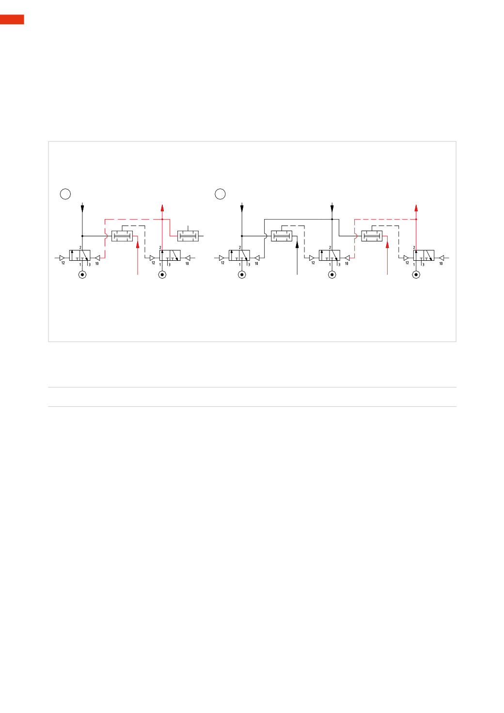
Figure 98
Pos. 4
: in addition to the functions described above, output
U2
feeds the input of a new
AND
function.
Even if signal
S1
is present, there is no output from the
AND
function because there is no input
U1
.
Pos. 5
: the main valve operated by output
U2
dictates the movements of some of the actuators, this movement
must be detected by a limit switch e.g., whichwill generate an output signal.
This signal becomes
S2
which is the input of thenew
AND
function, activating it operates thememory valve of the
subsequent sequencer and output
U3
is generated. As inPos 3, output
U3
, besides being used as a pilot signal to
the valves in the circuit, has the function of closing the
3/2-way
memory valve that generated
U2
. As thememory
valve closes, the output of
U2
is exhausted and consequently also the pilot signal
12
of thememory valve which
generated output
U3
.
U1
U2
U1
U2
U3
S1
S1
S2
4
5
Fig. 98
After illustrating the operating principles, we analyze how to use them to develop a sequence. The sequence to be
realized is:
A+ / B+ / B – / C+ / C – / A –
Conditions:
initiatewith Start Cycle button
I.C.
Selection of main valves:
Cylinder
A
: the
bistable
function is preferred, as the cylinder remains in the positive end position for almost the
entire sequence.
Cylinders
B
and
C
: in this case a
monostable
function is preferred.
This sequence incorporates blocking signals also:
a1
is present during both the
B+
stroke and the
B –
stroke
b0
is present during both the
C+
stroke and the
C –
stroke
c0
is present during both the
A –
stroke and the
A+
stroke
Using the sequencer all these signals can be ignored.
Typically, this circuit represents the system at rest, (start position). Both the limit switches and the main valves
that operate the cylinders are powered by themain compressed air network.
Figure 99
Pos. 1
: thememory valve in the
first
sequencer (
MS1
) is open, its output is defined as
U1
, it feeds the
I.C.
button
and the logic
AND
element of the second sequencer (
MS2
).
The
Start
command is provided by the activation of the
I.C.
, it operates the main valve of cylinder
A
and allows
this piston rod/piston to execute the positive stroke
A+
.
Pos. 2
: once the
A +
stroke has reached its positive end position, limit switch
a1
is actuated, and its output
together with
U1
, is connected to the two inlets of the logic
AND
element (
MS2
). The output of the
AND
element
operates thememory valve, which, by opening the passage, generates
U2
.
With the activation of the
U2 Line
, we have:
• the operation of themain valve of cylinder
B
in order to obtain
B+
• the reset of thememory valve of the sequencer
MS1
and the consequent interruption of
U1
• preparation of the
AND
function of sequencer
MS3
.
The
U2 Line
remains active until the activation of limit switch
b1
, which detects the arrival at position
B+
.
5
188
CAMOZZI
>
CIRCUIT TECHNIQUE