


 187 / 218

CIRCUIT TECHNIQUE
+
+
-
D
+
-
C
+
-
B
-
A
I.C.
1 2 3
5 4
6
1
7
8
a1
c1
d1
U1 * I.C. * b0 = A+
U1 * a1 = S2 = U2 = A-
U2 * a0 = B+
U2 * b1 = C+
U2 * c1 = S3 = U3 = C-
U3 * c0 = D+
U3 * d1 = S1 = U1 = D-
b1
a0
c0
Cil. "A"
Cil. "B"
Cil. "C"
Cil. "D"
a0 a1
b0 b1
c0 c1
d0 d1
b0
a1
a0
c1
d0
b1
c0
d1
I.C.
U1
U2
U3
U1
U2
U3
S1
S3
S2
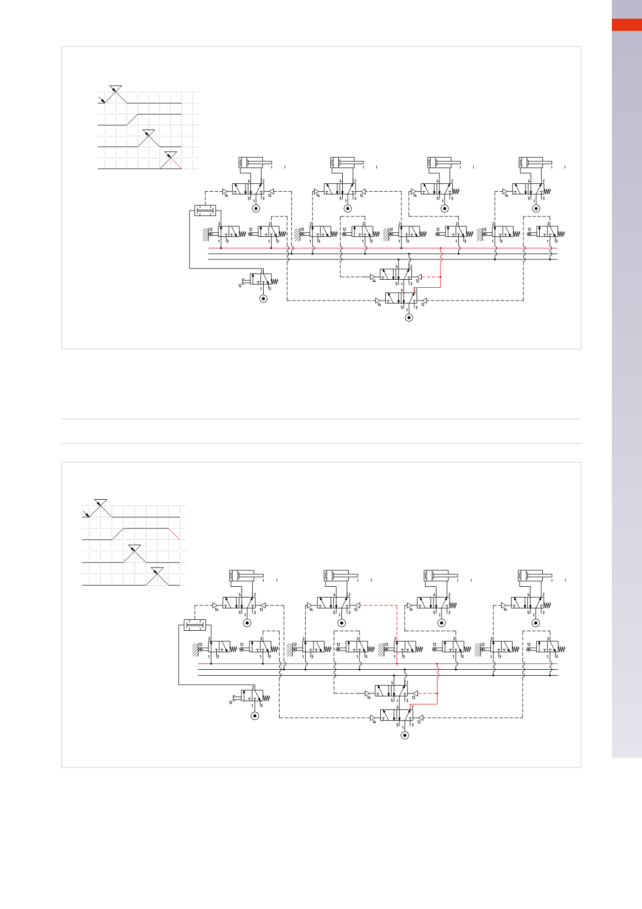
Fig. 94
Figure 95
Phase 8
: the piston rod/piston of cylinder
D
completes the negative stroke, reaches and activates limit switch
d0
,
whose output operates the valve of cylinder
B
, permitting the piston rod/piston to complete the negative stroke.
U1 * d0
=
B -
+
+
-
D
+
-
C
+
-
B
-
A
a1
c1
d1
b1
a0
c0
d0
b0
I.C.
U1 * I.C. * b0 = A+
U1 * a1 = S2 = U2 = A-
U2 * a0 = B+
U2 * b1 = C+
U2 * c1 = S3 = U3 = C-
U3 * c0 = D+
U3 * d1 = S1 = U1 = D-
U3 * d0 = B-
Cil. "A"
Cil. "B"
Cil. "C"
Cil. "D"
a0 a1
b0 b1
c0 c1
d0 d1
b0
a1
a0
c1
d0
b1
c0
d1
I.C.
U1
U2
U3
U1
U2
U3
S1
S3
S2
1 2 3
5 4
6
1
8
7
Fig. 95
The cycle has completed and we return to the initial state with
U1
active, the position of cylinder
B
is confirmed,
and the sequence is ready for a new cycle.
Unwanted movements are a possibility in the event of unintended activation of certain limit switches if powered
by the main network. Besides blocking signals, also the possibilies are avoided however by applying the technique
with memories in cascade. The use of monostable valves must always be evaluated, particularly for the control of
actuators with gripping or locking functions.
5
185
CAMOZZI
>
CIRCUIT TECHNIQUE