


 192 / 218

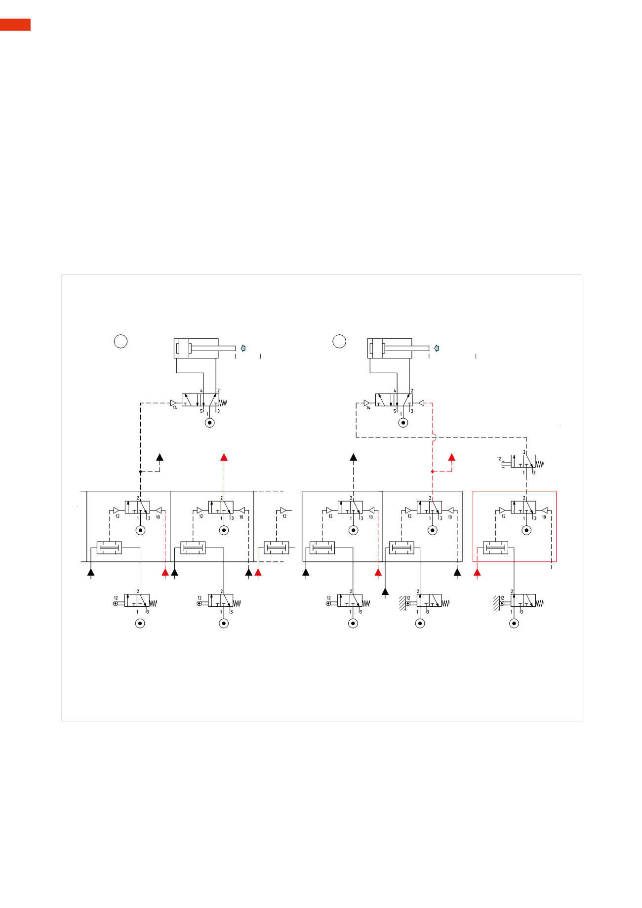
Figure 101
Pos. 5
: once the piston rod/piston of cylinder
C
has completed its positive stroke, it actuates limit switch
c1
,which
emits an output signal. This signal, together with the confirmation of the presence of
U4
is connected to the two
inlets of the
AND
element of sequencer
MS5
. The output of the
AND
operates thememory valvewhich generates
LineU5
by opening the passage.
With the activation of the
LineU5
we have:
• The reset of the memory valve of sequencer
MS4
and consequently the interruption of
U4
, the changing over
of the main valve of cylinder
C
(monostable) and the return of the piston rod/piston of cylinder
C
at the negative
end position.
• Preparation of the
AND
function of sequencer
MS6.
Pos. 6
: once the piston rod/piston of cylinder
C
has completed its negative stroke, it actuates limit switch
c0
,
which emits an output signal. This signal, together with the confirmation of the presence of
LineU5
, is connected
to the two inlets of the
AND
element of sequencer
MS6
. The output of the
AND
operates thememory valvewhich
generates
LineU6
by opening the passage.
With the activation of the
LineU6
we have:
• the operation of themain valve of cylinder
A
in order to obtain
A –
• the reset of thememory valve of sequencer
MS5
and the consequent interruption of
U5
• preparation of the
AND
function of sequencer
MS1
.
c1 *U4=
U5
=C
-
c0 *U5=
U6
=A
-
c0 c1
b0
c1
U4
a0
a1
c1
U5
U6
c0
U1
U6
a0
I.C.
Cil. "C"
U4
MS4
MS5
MS6
U4
U6
U3
U5
U4
U6
U5
U5
U5
MS5
Cil. "A"
MS1
MS6
U6
5
6
Fig. 101
Figure 102
The piston rod/piston of cylinder
A
actuates the limit switch
a0
when it reaches its terminal position. The output of
a0
and
U6
are connected to the
AND
function of sequencer
MS1
which generates the output. This output signal
operates thememory valvewhich by changing over, generates
LineU1
.
With the activation of the
U1
Line
, we have:
• compressed air supply for the
I.C.
button for the beginning of a new cycle
• the reset of thememory valve of sequencer
MS6
and subsequent interruption of
LineU6
.
The cycle has been completed, the sequencer is ready for a new cycle, the blocking signals do not interfere and
the development/drawing of the circuit is simplified.
The number of sequencers to be used corresponds to the number of phases in the sequence.
5
190
CAMOZZI
>
CIRCUIT TECHNIQUE