


 145 / 218

CIRCUIT TECHNIQUE
Fig. 20
Elementary circuits
In previous circuits, we used
5-way
/
2-positions
as main valves and
3-way
/
2-positions
as limit switches (pilot
valves). In this sectionwe use the
5-way
/
3-position
valves, which can have three positions:
Closed Centers (CC)
,
Open Centres (OC)
, and
Pressure Centres (PC)
.
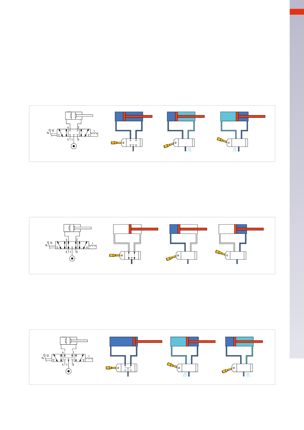
Figure 20
Closed Centers(CC)
In this state all connections on the valve are intercepted and closed. By blocking both the incoming and the
outgoing compressed air from the cylinder, it remains trapped inside andmoves the piston rod/piston until there
is an equilibrium of pressure within the two chambers. At this point, themovement stops. This condition is to be
consideredneither stablenor safe. Any leak from the seals, either from thepiston, the connection fittings, the valve
or the breakage of a connection tube, would create a pressure difference in the chambers of the cylinder and the
consequent movement of the piston rod/piston.
Figure 21
Open Centers (OC)
Inlet 1 of the compressed air is closed; the two outlets 2 and 4 are connected to the cylinder chambers, open
towards the exhaust ports3and5. There is atmospheric pressure in the cylinder chambers, andas a consequence,
the piston rod/piston is free tomove. Note: once the piston resumes its movement after it has stopped in the OC
position of the valve, it is no longer controllable as there is no compressed air in the exhaust chamber. An eventual
flow regulation valvewould not function properly.
Fig. 21
Figure 22
Pressure Centers (PC)
The two cylinder chambers are pressurized, the different thrust area on the piston of the cylinder due to the
presence of the rod, gives a resulting forcewhereby the piston rod/pistonmoves towards the positive end position.
In this case the value of the applied load is also relevant, if it is greater than the resultant (force) the piston rod/
piston will remain stationary. This function can be applied for example in the movement of a door which can be
openedmanually with a reduced force in the case of an emergency.
Fig. 22
The electrically and pneumatically operated 3 position valves aremonostable, the third position is obtained in the
absence of apilot signal due to the effect of return springs. Manual valves can be monostable or bistable, their
positions are determined by the operator.
5
143
CAMOZZI
>
CIRCUIT TECHNIQUE