


 154 / 218

The basic logic functions
The rules of logic that imply a
0
or
1
status adapts well to pneumatically operated valves.
The principle logic functions pneumatically obtainable are:
YES
;
NOT
;
AND
;
OR
.
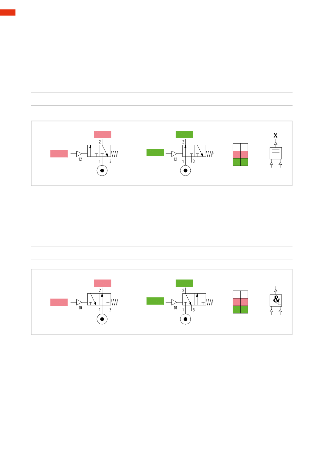
Figure 39
YES
function
The valve which achieves this function is a
monostable 3/2-way NC
valve. Let “
a
” indicate the
0
or
1
status of
the pilot signal, let
X
indicate the
0
or
1
status of the outlet signal from outlet 2;
If
a
=
0
then
X
=
0
; if
a
=
1
then
X
=
1
X= a
Figura 41
AND
function
This valvewill only give an output signal if the two pilot signals are present.
There is an output signal
X
only if
a
=
1
and
b
=
1
.
The presence of two pilot signals, whereby eachmay have two states, brings the total of possible combinations to
four, but only in one of them does the variable
X
have status
1
.
If
a
=
0
and
b
=
0
then
X
=
0
; there are no signals present
If
a
=
1
and
b
=
0
then
X
=
0
; the input signal moves the internal piston
to the right preventing passage towards
X
If
a
=
0
and
b
=
1
then
X
=
0
; the input signal moves the piston
to the left preventing the passage towards
X
If
a
=
1
and
b
=
1
then
X
=
1
; if the pressures are equal, themost recent signal passes,
if the pressures are different the signal with the lower pressure passes.
a X
0 0
1 1
X
a 1
X=0
X= 1
a=0
a=1
Fig. 39
Figure 40
NOT
function
The valve which achieves this function is a
monostable 3/2-way NO
valve. Let “
a
” indicate the
0
or
1
status of
the pilot signal, let
X
indicate the
0
or
1
status of the output signal at outlet 2;
If
a
=
0
then
X
=
1
; if
a
=
1
then
X
=
0
a
=
0
, when the information “
a
” is not present (FALSE), then
X
=
1
(it is present, TRUE)
aˉ= X
a X
0 1
1 0
X
a 1
X= 1
X= 0
a= 0
a= 1
Fig. 40
5
152
CAMOZZI
>
CIRCUIT TECHNIQUE