


 150 / 218

Phase 4 in the previous paragraph this was not taken into consideration as it could create two different working
modes:
single
cycle or
continuous
.
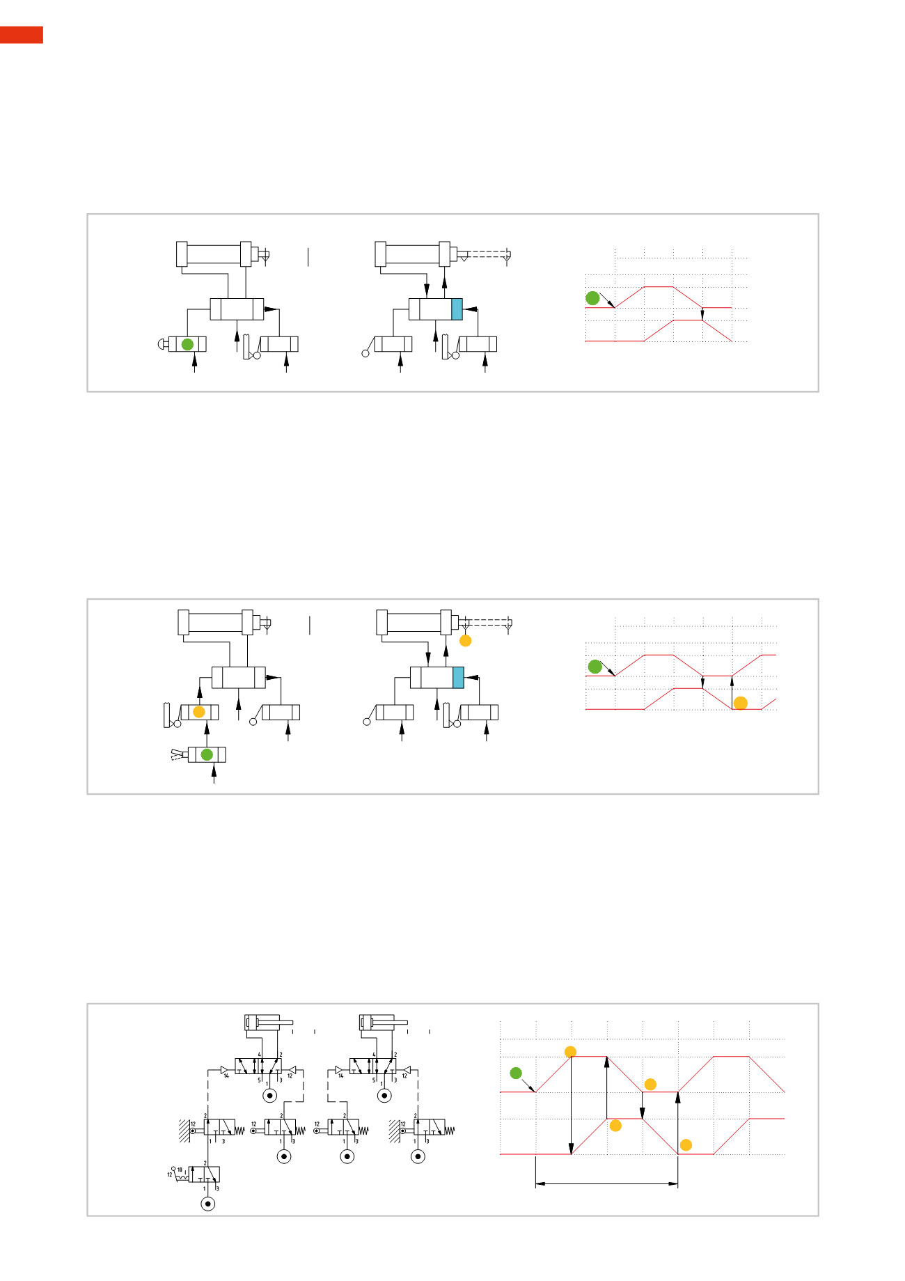
Figure 31
Phase 4
:
Single Cycle
The signal generated by the limit switch
a0
changes the position of the valve
P
B
,
the piston rod/piston of cylinder
B
returns to its initial position, the cycle stops where there is no limit switch. In Phase 1, the start signal to the
valve
P
A
is provided by amanually operatedmonostable 3/2-way NC valve powered directly by the network.
a1
b1
P
A
a0
a1
P
B
a0
b1
a1
+
A
_B
_
+
A
1
a0
b1
B
2 3 4
I.C.
I.C.
Fig. 31
Figure 32
Phase 4
:
Continuous Cycle
The signal generated by the limit switch
a0
changes the position of valve
P
B
, the piston rod/piston of cylinder
B
returns to its initial position and actuates the limit switch
b0
(absente before).
Note
: Note that in the flow diagram, the output signal from the limit switch
b0
enables the restart of the piston
rod/ piston of cylinder
A
.
The limit switch
b0
is fed by themanually operated bistable 3/2-way NC valve
I.C.
If the valve
I.C.
is in the open
position andwith the actuation of the limit switch
b0
, the compressed air reaches the pilot signal of themain valve
P
A
for the repetition of the cycle.
a1
a1
b1
a0
+
A
_B
_
+
A
1
b0
a1
a0
b1
2
a0
b1
b0
B
2 3
1 4
I.C.
I.C.
b0
P
A
P
B
Fig. 32
As observed in Phases 2, 3 and 4, the continuing duration of the actuation on the limit switches and consequent
presence of the output signals
does not obstruct the cycle
. It is important to take note of the relationship between
movements
and
signals
, essential for the resolution of the circuits.
Figure 33
We examine the continuous cycle as an example:
to obtain the stroke
A+
the output signals from
I.C.
and
b0
are necessary
to obtain the stroke
B+
the output signal from
a1
is necessary
to obtain the stroke
A –
the output signal from
b1
is necessary
to obtain the stroke
B –
the output signal from
a0
is necessary.
b0
a1 a0
A
B
b1
_
A
+
B
_
+
b1
a1
1 2 3
a0
b0
1 4
2 3
cycle
I.C.
b0
b1
a1
a0
I.C.
Fig. 33
5
148
CAMOZZI
>
CIRCUIT TECHNIQUE