


 151 / 218

CIRCUIT TECHNIQUE
Wemodify the previous sequence from:
A+ / B+ / A – / B –
to
A+ / B+ / B – / A –
1
2
3
4
1
2
3
4
which is operatingwith a continuous loop.
Anew analysis of the circuit from the beginning of Phase2 is required due to the change inmovements of the last
two phases of the circuit.
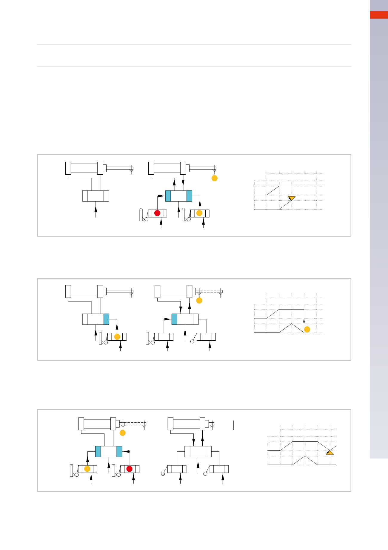
Figure 34
Phase 2
: the signal generated by the limit switch
a1
changes the position of valve
P
B
, the piston rod/piston of
cylinder
B
reaches thepositiveendpositionandactuates the limit switch
b1
, the limit switch
b1
generates a signal
which allows the immediate return of the piston rod/piston of cylinder
B
. The signal
b1
cannot change the position
of valve
P
B
as the signal from the switch
a1
is still present, being actuated by the piston rod of cylinder
A
still in
this position. In order for the sequence to continuewe need to remove the output signal from the limit switch
a1
.
a1
P
A
a1
P
B
b1
a1
+
A
_B
_
+
A
1
b1
B
2 3 4
b1
Fig. 34
Figure 35
Phase3
:we assume thatwe have removed
a1
(methodwill be shown later) and proceedwith the cycle. The valve
P
B
changes position, the piston rod/piston of cylinder
B
returns and activates the limit switch
b0
.
a1
a1
P
A
+
A
_B
_
+
A
1
b0
a1
P
B
b1
b1
b1
B
2 3 4
b0
b0
Fig. 35
Figure 36
Phase 4
: the signal generated by the limit switch
b0
changes the position of valve
P
A
and the piston rod/piston of
cylinder
A
returns to the start position. Once the cylinder
A
has returned to the start position, the limit switch
a0
is actuated again.
a0
b0
+
a1
P
A
b0
A
B_
+
A_
a1
P
B
b0
b1
B
a0
a1
1 2 3 4
b1
b1
a0
Fig. 36
The cycle should be repeated but cannot continue due to the presence of the pilot signal
b0
on the valve
P
A
preventing it from changing over, similar toPhase2where the signal is generated by the switch
a1
, these types of
signals are called “
blocking signal
”. The signal generated by the switch
b1
and
a0
is
instantaneous
.
5
149
CAMOZZI
>
CIRCUIT TECHNIQUE